
Seeding tray structure assembly and seeding device

A technology for structural components and seeding devices, applied in the directions of planter parts, sowing, planting methods, etc., can solve the problems of not being able to simply replace the use, the damage rate of damaged seeds, and the increased cost of mechanized equipment, and achieve the path for seeds to enter the hole. Smooth, conducive to membrane perforation, saving manpower and material resources

Pending Publication Date: 2020-07-31
王政
View PDF0 Cites 0 Cited by
  • Summary
  • Abstract
  • Description
  • Claims
  • Application Information

AI Technical Summary

Problems solved by technology

[0004] (1) Different sowing structures need to be manufactured for different crops. The planting adaptability of the seeder is poor, and it cannot be simply replaced. For example, the seeder for planting peanuts is used to remove vegetable seeds. This problem leads to an increase in the cost of mechanized equipment and a variety of crops. Growth had to be equipped with different seeders;
[0005] (2) For film-covered cultivation, it is necessary to manually break the film and release the seedlings, otherwise the phenomenon of high-temperature scalding will occur, which greatly increases the labor force;
[0006] (3) The internal structure of the existing seeder is easy to damage the seeds, resulting in high damage rate, which cannot meet the requirements of farmers for sowing;
[0007] (4) The precision sowing effect of the existing seeders is poor, and it is difficult to achieve one-by-one. Most of them are continuous linear or continuous planar, and different crops have different growth environment requirements, which affects crop production capacity;
[0008] (5) There is a seed passage in the duckbill-type punching head on the market, and grass and mud are caught during the seed spit process of duckbills opening and closing, which affects the quality of sowing;
[0009] (6) As long as the plant spacing of the existing seeder is set, it cannot be adjusted, and the adaptability to different varieties is poor;

Method used


Image

  • Seeding tray structure assembly and seeding device
  • Seeding tray structure assembly and seeding device
  • Seeding tray structure assembly and seeding device

Examples


Embodiment 1

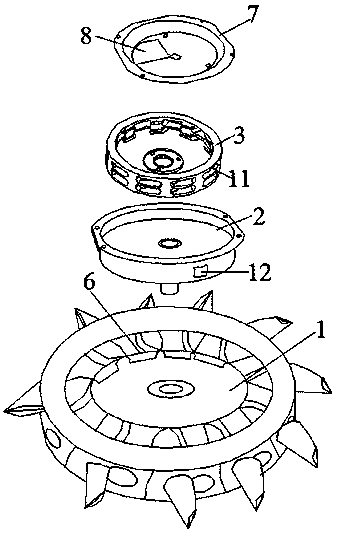
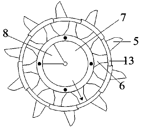
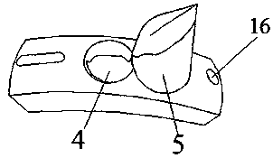
[0052] like Figure 1-8 As shown, a kind of sowing disk structure assembly includes an outer sowing disk 1, a fixed disk 2 and a seeding screen 3, and the outer sowing disk 1, the fixed disk 2 and the seeding sieve 3 shaft holes are on the same axis, and the outer sowing disk 1 is embedded with There is a fixed disc 2, the side wall of the fixed disc 2 is provided with a seeding hole 12, the seeding screen 3 is placed in the fixed disc 2, and the outer sowing disc 1, the fixed disc 2 and the seeding screen 3 are integrally fixedly connected by a screw nut, and finally The fixed state is that when the fixed disk 2 is erected, the horizontal plane is used as a reference, and the seed hole 12 on the fixed disk 2 is on the lower end side wall, and the angle formed with the horizontal plane is 10-30 ° (see Figure 7 ), the upper end of the fixed disk 2 is fixedly connected with the cover plate 7, and the outer side of the outer broadcast disk 1 includes ten arc-shaped engaging plat...

Embodiment 2

[0055] like Figure 9 As shown, embodiment 2 is a further improvement to the technical solution of embodiment 1. The inside of the seeding screen 3 is provided with a seed cleaning sheet 9, and the seed cleaning sheet 9 includes a guide sheet 901, and the outside of the guide sheet 901 matches the radian of the inside of the seeding screen 3. The outer side of the linear guide end of the lower end of the guide piece 901 is symmetrically provided with a single arc-shaped protrusion-902, and the single-arc-shaped protrusion-902 is placed in the seed hole-11 of the seeding screen 3. The benefit of this design is that the seeding of the seeding screen 3 The seeds in the hole 11 are cleaned out, and the guide sheet 901 acts as a seed guide; the principle of the so-called seed cleaning sheet 9 in this part is that when seeds such as peanuts enter the seed outlet 11 of the seeding screen 3, they will stay inside , and the function of seed clearing sheet 9 is exactly that seed is sque...

Embodiment 3

[0057] like Figure 10 As shown, embodiment 4 is a further improvement to the technical solution of embodiment 3. The seed cleaning sheet 9 includes a guide sheet 901, the outside of the guide sheet 901 matches the radian of the inner side of the seeding screen 3, and the outer side of the straight guide end of the lower end of the guide sheet 901 is symmetrically arranged. Continuous two-step arc-shaped protrusions 903, the two-step arc-shaped protrusions 903 are placed in the seed outlet 11 of the seeding screen 3, the advantage of the two-step arc-shaped protrusions 903 compared with a single arc-shaped protrusion 902 is that it can damage the seeds Small, because the existing single arc-shaped protrusion-902 on the market is a structure that matches the seed hole-11 of the seeding screen 3, the radian is steep, and the seeds will be squeezed by the single arc-shaped protrusion-902 when passing through the seed hole-11 pressure, thereby damaging the seeds, and after the sin...


PUM


Abstract

The invention discloses a seeding tray structure assembly. The seeding tray structure assembly comprises an outer seeding tray, a fixed tray and a seeding sieve, wherein the outer seeding tray, the fixed tray and a shaft hole of the seeding sieve are located in a same axis, the fixed tray is embedded in the outer seeding tray, a seed discharging hole is formed in the side wall of the fixed tray, the seeding sieve is placed in the fixed tray, the upper end of the fixed tray is fixedly connected with a cover plate, the outer side of the outer seeding tray comprises multiple arc-shaped clamping plates which are fixed through clamping and define a disc shape, seed leaking holes and punching heads next to the seed leaking holes are formed in the arc-shaped clamping plates, seed guide pipes communicating with the multiple seed leaking holes in a one-to-one correspondence manner are arranged in the outer seeding tray, and a seed feeding hole is formed in the cover plate. Compared with a traditional seeding device, the device facilitates multigroup and large operation, is particularly suitable for large-area operation, and is closer to use reality and suitable for promotion and use.

Description

technical field [0001] The invention relates to a sowing device, in particular to a sowing disc structural component and a sowing device. Background technique [0002] With the advancement of science and technology and the increase of human capital, mechanized planting has become the mainstream trend. Not only is it not as simple as manpower, it takes less time, but also because mechanized farming is more scientific, and the spacing of sowing is more uniform, the depth is also consistent, and the distance between plants The row spacing is relatively stable, the soil is well covered, the efficacy is high, and most importantly, seeds are also saved. Many advantages have already ensured that the crops grow into seedlings; at the same time, it is conducive to saving labor, and can ensure crop planting, care and harvesting, etc. The link does not miss the farming time, which is beneficial to reduce the loss of crops; farm mechanization can save manpower, material resources and fi...

Claims


Application Information

Patent Timeline
Patent Type & Authority Applications(China)
IPC IPC(8): A01C7/20A01C7/00A01C5/04
CPCA01C7/20A01C7/00A01C5/04
Inventor 王政
Owner 王政
Learn More