A parabolic trough solar collector

A trough-type solar collector technology, which is applied in solar collectors, solar collectors using working fluid, solar thermal energy, etc., can solve the problems of heavy installation and commissioning, high mirror damage rate, and light conversion efficiency. Low-level problems, to achieve the effects of reduced maintenance costs, high light-gathering efficiency, and low process requirements

Active Publication Date: 2021-08-31
GUANGZHOU LIYANG ENERGY TECH CO LTD
View PDF0 Cites 0 Cited by
  • Summary
  • Abstract
  • Description
  • Claims
  • Application Information

AI Technical Summary

Problems solved by technology

[0003] In a trough parabolic solar concentrator, it generally includes: a heat-absorbing component, a parabolic reflector, a supporting device and a matching sun tracking device; the reflector is formed of a parabolic reflective material, and the heat-absorbing component The heat collecting tube is located on the focal line of the paraboloid; as an important part, the heat absorbing component is required to have a high absorption rate, and at the same time, it is easy to manufacture; at present, the reflector of the existing trough solar collector adopts a formed reflector pasted on a hot-bent formed Manufactured by the method on tempered glass, the product is easily deformed. Due to the deformation stress of the mirror, the tempered glass will explode in application, and the mirror damage rate is high.
And the manufacturing process cost is relatively high, the workload of installation and debugging is relatively large, and the production cost is high
[0004] In addition, studies have shown that the photoelectric conversion efficiency of existing heat collectors is about 11%, while the photothermal conversion efficiency is only about 50%, and the photoelectric conversion efficiency is relatively low.

Method used


Image

  • A parabolic trough solar collector
  • A parabolic trough solar collector
  • A parabolic trough solar collector

Examples


Embodiment Construction

[0033] DETAILED DESCRIPTION OF THE INVENTION The specific embodiments of the present invention will be further described below with reference to the accompanying drawings:

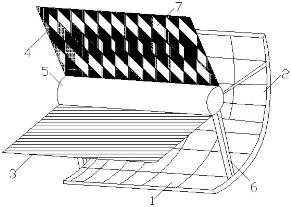
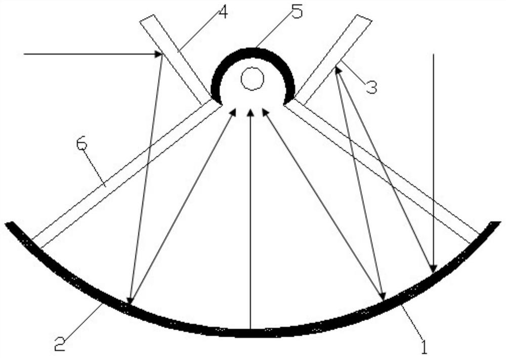
[0034] like figure 1 with figure 2 , The present embodiment provides one kind of parabolic trough solar collector assembly 6 comprises a support, a reflective assembly endothermic assembly 5, the assembly comprises a first reflecting parabolic concentrator trough 1 and a second parabolic concentrator trough 2, and a first plane mirror 3 and second flat mirror 4, the first plane mirror 3 and second flat mirror 4 are laid in the first trough and a second parabolic concentrator trough parabolic concentrator reflective front end 2; and a first plane mirror 3 and second flat mirror or a polygon defines a plurality of strip 4 into the aperture 7, the sun's rays directly incident through the aperture 7 into stripe or polygon to the entrance aperture 7 a first parabolic concentrator trough parabolic trough 1 and a sec...


PUM

PropertyMeasurementUnit
thicknessaaaaaaaaaa
photothermal conversion efficiencyaaaaaaaaaa

Abstract

The invention provides a parabolic trough solar heat collector, which includes a support assembly, a reflection assembly, and a heat-absorbing assembly. Reflective mirror, the first flat reflective mirror and the second flat reflective mirror are respectively arranged on the reflective surface front ends of the first trough parabolic condenser and the second trough parabolic condenser; A strip-shaped or polygonal incident hole, the heat-absorbing component is arranged on the reflective component through the support component; the present invention has high light-gathering efficiency; the elliptical cavity is used as a black body cavity, the light reflection effect is good, the heat loss is small, and the process Low requirements are conducive to mass production; the outer surface of the heat collecting tube is coated with an anti-reflection coating to improve the heat collecting effect; through the cooperation of the parabolic concentrator and the plane reflector, the sun's rays can be fully utilized, which greatly improves the light and heat of the heat collecting component conversion rate.

Description

Technical field [0001] Technical Field The present invention relates to a solar apparatus, in particular a parabolic trough solar collectors. Background technique [0002] Solar energy as a renewable energy, comprising clean, efficient characteristics, widely used around the world; concentrating collector technology is a major way to the development and utilization of solar energy, wherein the trough solar concentrating collector current technology development is the hottest and with commercial prospects condenser thermal technology, using parabolic trough solar concentrator collection of absorption. [0003] In parabolic trough solar concentrator collectors in general, comprising: a heat absorbing component, a parabolic mirror, and a support device supporting the solar tracking apparatus; wherein the parabolic reflector is formed from a reflective material, heat sink assembly parabolic collector tube located in the focal line; absorbing member as an important component, required...

Claims


Application Information

Patent Timeline
Patent Type & Authority Patents(China)
IPC IPC(8): F24S10/40F24S10/70F24S23/71F24S23/77F24S70/20
CPCF24S10/40F24S10/70F24S23/71F24S23/77F24S70/20Y02E10/44
Inventor 唐志军汤荣华汤问天
Owner GUANGZHOU LIYANG ENERGY TECH CO LTD
Why Eureka
Try Eureka