
Upper power tube conduction time timing circuit with wide input voltage range

A technology of on-time and voltage range, applied in the field of the on-time timing circuit of the upper power tube, can solve the problems of changing the on-time adjustment, not adapting to a wide voltage input range, etc., to ensure the image accuracy and improve the withstand voltage characteristics. Effect

Active Publication Date: 2020-07-31
UNIV OF ELECTRONICS SCI & TECH OF CHINA
View PDF5 Cites 6 Cited by
  • Summary
  • Abstract
  • Description
  • Claims
  • Application Information

AI Technical Summary

Problems solved by technology

[0003] Aiming at the inadequacies in the traditional COT switching power supply's upper power tube conduction time generation method that is not suitable for wide voltage input range and cannot accurately follow the input and output voltage changes of the switching power supply to adjust the conduction time, the present invention proposes a power The tube conduction time timing circuit has a wide input voltage range and is suitable for controlling the conduction time of the upper power tube in the COT mode switching power supply. By reflecting the information of the input voltage VIN of the COT switching power supply to the conduction time of the upper power tube, It can make the COT switching power supply obtain a switching frequency that is positively correlated with its output voltage VO, thereby effectively improving the efficiency of the COT switching power supply at low input voltage and reducing the output ripple at high output voltage

Method used


Image

  • Upper power tube conduction time timing circuit with wide input voltage range
  • Upper power tube conduction time timing circuit with wide input voltage range
  • Upper power tube conduction time timing circuit with wide input voltage range

Examples


Embodiment Construction

[0032] The technical solution of the present invention will be described in detail below in conjunction with the accompanying drawings and specific embodiments.

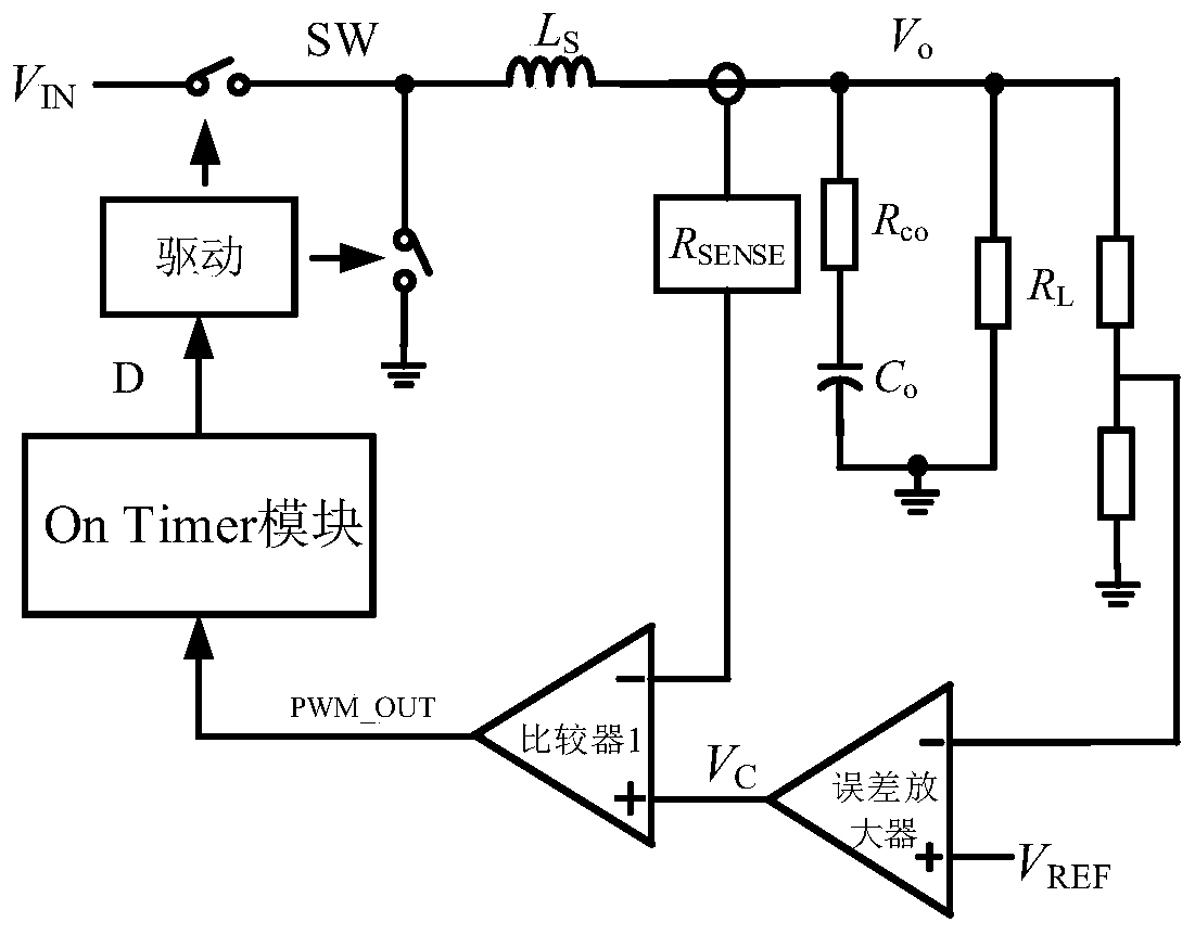
[0033] COT switching power supplies often use pulse width modulation (PWM) to control the on and off of the upper power tube and the lower power tube, such as figure 1Take the buck converter of current mode COT as an example for illustration. One end of the upper power tube is connected to the input signal VIN of the COT switching power supply, the other end is connected to one end of the lower power tube, and the other end of the lower power tube is grounded. The connection of the power tube passes through the inductor to obtain the output signal VO of the COT switching power supply; the output signal VO is divided by a resistor to obtain a feedback signal and a reference signal VREF for error amplification, and then compared with the sampling value of the inductor current to obtain the pulse width The modulation si...


PUM


Abstract

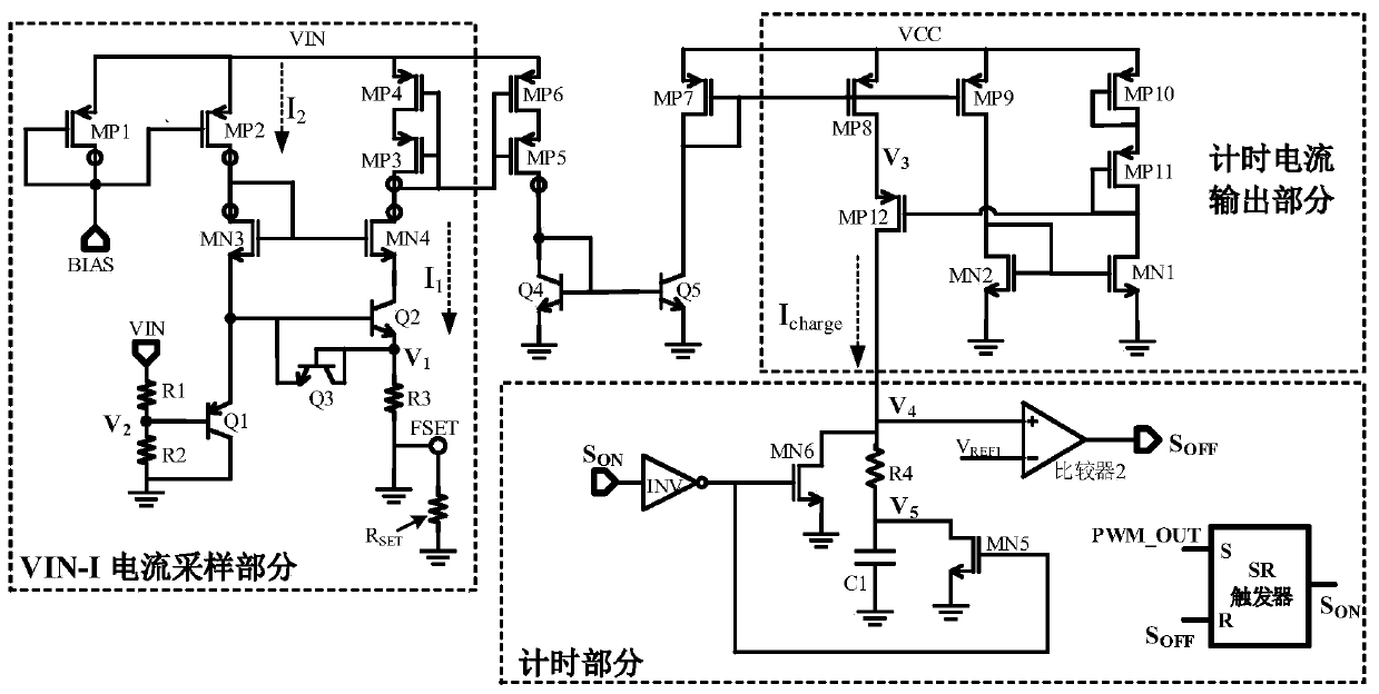
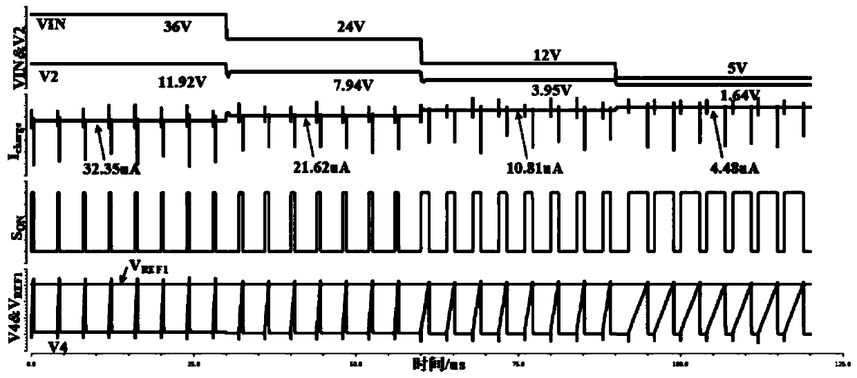
The invention discloses an upper power tube conduction time timing circuit with a wide input voltage range. The circuit comprises an input voltage sampling module, a timing current output module and atiming module. The input voltage sampling module is used for sampling an input voltage of the COT switching power supply and converting the input voltage to obtain a sampling current. The timing current output module generates timing current according to the sampling current; and the timing module charges the timing capacitor by using timing current after an upper power tube of the COT switchingpower supply is conducted, compares voltage on the timing capacitor with reference voltage by using the comparator, generates a turn-off signal of the upper power tube when the voltage on the timing capacitor is greater than the reference voltage, and discharges the timing capacitor. The input voltage information of the input COT switching power supply is reflected to the conduction time of the upper power tube, so that the COT switching power supply obtains the switching frequency positively related to the output voltage, the efficiency of the COT switching power supply at low input voltage can be effectively improved, and the output ripple of the COT switching power supply at high output voltage can be reduced; and the upper power tube conduction time timing circuit has a wide input voltage range and high mirror image precision.

Description

technical field [0001] The invention belongs to the technical field of electronic circuits and relates to an upper power tube conduction time timing circuit, which can be used to control the upper power tube conduction time of a constant conduction time (COT) control mode switching power supply in a wide voltage input range. Background technique [0002] With the rapid development of electronic technology, electronic equipment requires a switching power supply (DC / DC) with good efficiency and fast transient response capability under various load conditions. The traditional PWM control method is difficult to meet the power performance requirements of the point load (POL). The constant on-time (Constant On Time, COT) control method is widely used in the industry due to its excellent transient response capability and high light-load efficiency. Has been widely used. However, in the generation method of the conduction time of the upper power transistor in the traditional COT co...

Claims


Application Information

Patent Timeline
Patent Type & Authority Applications(China)
IPC IPC(8): H02M3/10H02M1/08H02M1/06H02M1/14
CPCH02M3/10H02M1/08H02M1/06H02M1/14Y02B70/10
Inventor 明鑫张杰贾丽伟程政梁华黄佳晖王卓张波
Owner UNIV OF ELECTRONICS SCI & TECH OF CHINA
Learn More