Cooling system of data center machine room

A technology for data centers and cooling systems, which is applied in the field of thermal management and can solve problems such as heat discharge

Active Publication Date: 2020-07-31
南京艾科美热能科技有限公司
View PDF4 Cites 9 Cited by
  • Summary
  • Abstract
  • Description
  • Claims
  • Application Information

AI Technical Summary

Problems solved by technology

[0007] In view of the shortcomings and deficiencies of the existing technology, the present invention aims to provide a heat dissipation system for a data center computer room, which adopts a heat collection module to discharge the heat generated inside the computer room, and the flow self-strain mechanism adjusts the flow of the fluid so as to achieve precise control and solve t

Method used


Image

  • Cooling system of data center machine room
  • Cooling system of data center machine room
  • Cooling system of data center machine room

Examples


Embodiment Construction

[0046] In order to make the purpose, technical solution and advantages of the present invention clearer, the patent of the present invention will be further described in detail below with reference to the accompanying drawings and examples.

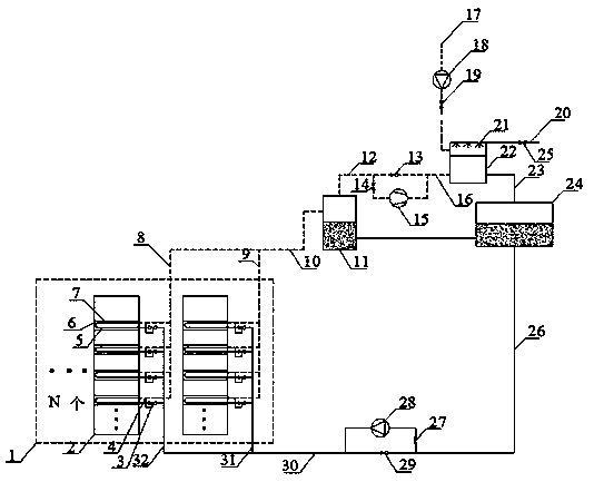
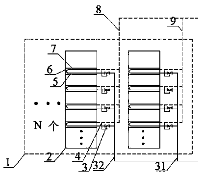
[0047] Such as figure 1 As shown, the heat dissipation system of the data center computer room of the present invention includes a computer room cooling system 1, a cabinet 2, a control mechanism 3, an induction mechanism 4, a fluid inlet pipeline 5, a card slot 6, a fluid outlet pipeline 7, and a steam branch pipeline 8 , steam branch pipeline 9, steam main pipeline 10, 12, 16, 23, gas-liquid separator 11, control valve 13, 14, 19, 27, 29, compressor 15, air inlet pipeline 17, fan 18, water supply pipe Road 20, spraying machine 21, radiator array 22, liquid storage tank 24, fluid pump 28, liquid sub-pipeline 31, liquid sub-pipeline 32. The entire heat dissipation system 1 includes n rows of cabinets. A card slot 6 is arranged between tw...


PUM


Abstract

The invention provides a heat dissipation system of a data center machine room. The heat dissipation system comprises heat collection modules, a gas-liquid separator, a liquid storage tank, a heat dissipation device and a fluid working medium, wherein the heat collection module, the gas-liquid separator, the liquid storage tank and the heat dissipation device form a heat dissipation circulating pipeline, the fluid working medium flows in the heat dissipation circulating pipeline, and the collection module comprises an evaporation section, a fluid inlet pipeline, a fluid outlet pipeline, a control mechanism, an induction mechanism and a steam branch pipeline. According to the invention, the data center machine room automatically switches the heat dissipation mode and the working mode to take away the heat generated by the evaporation end of the heat collection module according to the outdoor temperature condition and the thermal load condition of the machine room by taking energy consumption minimization as a target during operating; the flow is automatically adjusted through the flow self-strain mechanism of the heat collection module so as to solve the problem of heat production difference between the heat collection modules in the cabinet; and the refrigeration cycle, the gravity-driven self-cycle and the pump-driven two-phase flow cycle share a radiator array.

Description

technical field [0001] The invention patent relates to the field of thermal management. More specifically, the patent of the present invention relates to a heat dissipation system for a data center computer room. Background technique [0002] The integration density of cabinet servers in the data center computer room is getting higher and higher, and the calorific value is also increasing accordingly. The PUE (Power Usage Effectiveness, power usage efficiency) value has become a relatively popular measure of data center power usage efficiency in the world. The PUE value refers to the ratio of all energy consumed by the data center to the energy consumed by the IT load. The closer the PUE value is to 1, the higher the greenness of a data center. At present, the PUE value of foreign advanced data center computer rooms is usually less than 2, while the PUE value of most data centers in my country is between 2-3. Therefore, the 1W power consumption of the chip-level main equi...

Claims


Application Information

Patent Timeline
IPC IPC(8): H05K7/20
CPCH05K7/20718H05K7/20754H05K7/208H05K7/20836
Inventor 徐德好
Owner 南京艾科美热能科技有限公司
Why Eureka
Try Eureka