Catalytic regeneration flue gas denitrification, dust removal and desulfurization system and pressure reduction method

A technology for regenerating flue gas, denitrification and dust removal, applied in chemical instruments and methods, separation methods, general control systems, etc., can solve the problems of low piping difficulty, reduce boiler pressure, boiler pressure reduction, etc., and achieve low piping difficulty and low modification volume Small, the effect of increasing the operation of the same cycle

Active Publication Date: 2021-12-03
CHINA PETROLEUM & CHEM CORP
View PDF9 Cites 0 Cited by
  • Summary
  • Abstract
  • Description
  • Claims
  • Application Information

AI Technical Summary

Problems solved by technology

[0009] The purpose of the present invention is to overcome the large amount of modification of the water-sealed tank and related pipelines in the prior art, which cannot achieve the ideal effect of reducing the boiler pressure, and cannot adapt to the catalytic regeneration flue gas denitrification, dust removal and desulfurization system under emergency conditions. In order to solve the problem of control requirements, a catalytic regeneration flue gas denitrification, dust removal and desulfurization system and a pressure reduction method are provided. This method effectively reduces the outlet pressure of the smoke machine, the boiler pressure and reduces the The pressure difference between the outlet pressure of the economizer and the inlet pressure of the dust removal and desulfurization comprehensive tower (ΔP6=P7-P6)

Method used


Image

  • Catalytic regeneration flue gas denitrification, dust removal and desulfurization system and pressure reduction method
  • Catalytic regeneration flue gas denitrification, dust removal and desulfurization system and pressure reduction method
  • Catalytic regeneration flue gas denitrification, dust removal and desulfurization system and pressure reduction method

Examples


Embodiment approach

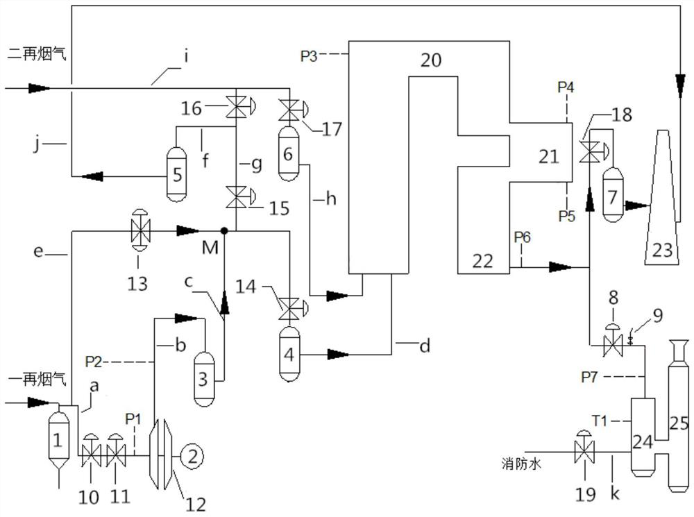
[0053] In the present invention, the system can be operated under various working conditions. In the first embodiment of the present invention, when the system is working normally, the high temperature gate valve 10, the high temperature butterfly valve 11, the first stop valve 14, the second The four cut-off valves 17 and the triple eccentric double butterfly plate butterfly valve 8 are opened to control the closing of the third cut-off valve 16, the second cut-off valve 15 and the fifth cut-off valve 18, the vent valve 9 and the quenching water valve 19, and the secondary flue gas is passed through the hood unit, boiler denitrification unit, through the triple eccentric double butterfly plate butterfly valve 8 and then into the chilling tower 24 and dust removal and desulfurization comprehensive tower 25 for denitrification, dust removal and desulfurization.

[0054] In the present invention, the secondary flue gas enters the boiler 20 of the boiler denitrification unit throu...

Embodiment 1

[0069] The original catalytic regeneration flue gas denitrification, dust removal and desulfurization system was transformed, and the position of the stop valve and water seal tank in front of the quenching tower was transformed into a triple eccentric double butterfly plate butterfly valve 8 and a vent valve 9.

[0070] The specific control process is: sequentially control the opening of the high temperature gate valve 10, the high temperature butterfly valve 11, the first stop valve 14, the fourth stop valve 17 and the triple eccentric double butterfly valve 8, control the third stop valve 16, the second stop valve 15, the The five stop valve 18, the vent valve 9 and the quenching water valve 19 are closed, and the angle of the triple eccentric double butterfly plate butterfly valve 8 is electrically adjusted to 90°, and the flue gas passes through the three-stage cyclone separator 1, and the solid is precipitated and then passed into the hood In the unit, open the high-tempe...

Embodiment 2

[0072] The original catalytic regeneration flue gas denitrification, dust removal and desulfurization system was transformed, and the position of the stop valve and water seal tank in front of the quenching tower was transformed into a triple eccentric double butterfly plate butterfly valve 8 and a vent valve 9.

[0073] The specific control process is: sequentially control the opening of the high temperature gate valve 10, the high temperature butterfly valve 11, the first stop valve 14, the fourth stop valve 17 and the triple eccentric double butterfly valve 8, control the third stop valve 16, the second stop valve 15, the The five stop valve 18, the vent valve 9 and the quenching water valve 19 are closed, and the angle of the triple eccentric double butterfly plate butterfly valve 8 is electrically adjusted to 90°, and the flue gas passes through the three-stage cyclone separator 1, and the solid is precipitated and then passed into the hood In the unit, open the high-tempe...


PUM


Abstract

The invention relates to the field of desulfurization and denitrification transformation of a catalytic cracking CO boiler, in particular to a catalytic regeneration flue gas denitrification, dust removal and desulfurization system and a pressure reduction method. It is characterized in that the system includes a smoke machine unit, a boiler denitrification unit, and a dust removal and desulfurization unit connected in sequence, wherein the dust removal and desulfurization unit includes a triple eccentric double butterfly plate butterfly valve, a vent valve, a quenching tower, and a dust removal and desulfurization unit that are connected in sequence. Integrated tower, this system is used to increase the pressure drop of the smoke machine unit and reduce the pressure of the boiler denitrification unit. Effectively reduces the pressure difference between the outlet pressure of the smoke machine, the boiler pressure, the outlet pressure of the economizer and the inlet pressure of the dust removal and desulfurization comprehensive tower (ΔP6=P7‑P6), which can adapt to the catalytic regeneration flue gas denitrification, dust removal and desulfurization system in emergency work According to the control requirements under the circumstances, the boiler and the catalytic main system can be operated at the same cycle to achieve a win-win situation of economic and environmental benefits.

Description

technical field [0001] The invention relates to the field of desulfurization and denitrification transformation of a catalytic cracking CO boiler, in particular to a catalytic regeneration flue gas denitrification, dust removal and desulfurization system and a pressure reduction method. Background technique [0002] FCC regeneration flue gas has a large volume, high temperature, and contains catalyst powder, which can easily cause wear and deformation of the butterfly valve. Therefore, the flue gas system of the catalytic cracking regeneration unit usually controls the entry and exit of the flue gas by setting a water-sealed tank, and the butterfly valve control as a supplementary control method. [0003] However, after the desulfurization and denitrification transformation of the catalytic cracking CO boiler, in order to ensure the feasibility and safety of each module of the boiler system (desulfurization, denitrification and dust removal), the flue gas system is equipped ...

Claims


Application Information

Patent Timeline
Patent Type & Authority Patents(China)
IPC IPC(8): B01D53/86B01D53/75B01D53/56B01D53/50G05B19/418
CPCB01D53/50B01D53/56B01D53/75B01D53/86B01D53/8609B01D53/8628B01D53/8631B01D2258/0283G05B19/41875
Inventor 华仲炯张忠海陈洁史尧林燕帅曾祺王松邓连水
Owner CHINA PETROLEUM & CHEM CORP
Why Eureka
Try Eureka