Eureka AIR delivers breakthrough ideas for toughest innovation challenges, trusted by R&D personnel around the world.

Distributed optical fiber sound wave and vibration fusion type sensing system

A distributed optical fiber, sensing system technology, applied in the measurement of ultrasonic/sonic/infrasonic waves, the use of wave/particle radiation, measurement devices, etc., can solve problems such as single vibration or acoustic wave sensing, to achieve cost savings, flexible operation, Easy-to-use effects

Active Publication Date: 2020-08-04
武汉光谷航天三江激光产业技术研究院有限公司
View PDF15 Cites 1 Cited by
  • Summary
  • Abstract
  • Description
  • Claims
  • Application Information

AI Technical Summary

Problems solved by technology

[0005] In order to overcome the shortcomings of conventional distributed optical fiber sensing equipment that only has a single vibration or acoustic wave sensing, the present invention provides a distributed optical fiber acoustic wave and vibration fusion sensing system, which integrates two functions of vibration and acoustic wave sensing

Method used


Image

  • Distributed optical fiber sound wave and vibration fusion type sensing system

Examples


Embodiment 1

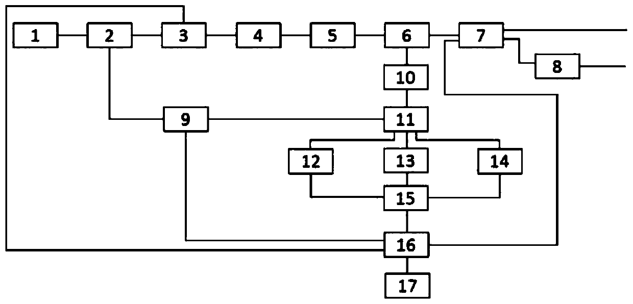
[0023] A distributed optical fiber acoustic wave and vibration fusion sensing system of the present invention, its structure includes a laser 1, a 1×2 optical fiber coupler 2, an acousto-optic modulator 3, an erbium-doped optical fiber amplifier 4, a first optical fiber filter 5, Optical fiber circulator 6, first optical switch, optical fiber Raman amplifier 8, second optical switch 9, second optical fiber filter 10, 3×3 optical fiber coupler 11, first photodetector 12, second photodetector 13 , the third photodetector 14, data acquisition and processing unit 15, computer 16, host computer software 17;

[0024] The laser 1, the 1×2 fiber coupler 2, the acousto-optic modulator 3, the erbium-doped fiber amplifier 4, the first fiber filter 5, the fiber circulator 6, the first optical switch, and the fiber Raman amplifier 8 pass through a single mode optical fiber, the optical fiber circulator 6, the second optical fiber filter 10, the 3×3 optical fiber coupler 11, the first photo...

Embodiment 2

[0044] Compared with Embodiment 1, the difference is that the laser 1 is a narrow linewidth laser.

[0045] All the other contents are the same as in Example 1.

Embodiment 3

[0047] Compared with Embodiment 2, the difference is that the power splitting ratio of the 1×2 fiber coupler 2 is 1:99, and the output power ratio of the first output port of the 1×2 fiber coupler 2 is 99. %, the output power ratio of the second output port of the 1×2 fiber coupler 2 is 1%.

[0048] All the other contents are identical with embodiment 2.


PUM


Abstract

The invention discloses a distributed optical fiber sound wave and vibration fusion type sensing system, which comprises a laser, a 1*2 optical fiber coupler, an acousto-optic modulator, an erbium-doped fiber amplifier, a first fiber filter, a fiber circulator, a first optical switch, a fiber Raman amplifier, a second optical switch, a second fiber filter, a 3*3 fiber coupler, a first photoelectric detector, a second photoelectric detector, a third photoelectric detector, a data acquisition and processing unit, a computer and upper computer software. The system has the advantages that two sensing functions and modes of vibration and sound wave sensing are fused, different working requirements can be met, the defect that conventional distributed optical fiber sensing equipment only has single vibration or sound wave sensing is effectively overcome, the cost is saved, and the sensing system is an important technical improvement in the field of distributed optical fiber sensing; flexibleswitching can be performed according to different use requirements and scenes, the cost is saved, and the use is convenient; and a mode of switching between a vibration mode and a sound wave sensing mode by means of controlling an optical switch is provided, and the operation is flexible.

Description

technical field [0001] The invention relates to the field of optical fiber sensing, in particular to a distributed optical fiber acoustic wave and vibration fusion type sensing system. Background technique [0002] Optical fiber sensor consists of light source, detection fiber, light modulator, light detector and demodulator. Its working process is to send the light of the light source into the modulation area through the incident optical fiber, and the light interacts with the external measured parameters in the modulation area to make the optical properties of the light (such as intensity, wavelength, frequency, phase, partial normal state, etc.) occur. It becomes modulated signal light, which is then sent to the optical detector and demodulator through the outgoing fiber to obtain the measured parameters. [0003] Distributed optical fiber sensor is a sensor that uses unique distributed optical fiber detection technology to measure or monitor the spatial distribution and...

Claims


Application Information

Patent Timeline
IPC IPC(8): G01H9/00
CPCG01H9/004
Inventor 孙志伟石冰馨邱秀分任杰汪元坤彭振洲刘波杨付飞
Owner 武汉光谷航天三江激光产业技术研究院有限公司
Why Eureka
Eureka Blog
Learn More