Fiber grating temperature/vibration/strain composite sensor and working method thereof

A composite sensor and fiber grating technology, applied in the field of composite sensors, can solve problems such as low resonance frequency and unfavorable measurement, and achieve the effects of improving accuracy and sensitivity, improving vibration measurement accuracy, and improving accuracy

Pending Publication Date: 2020-08-07
XI AN JIAOTONG UNIV +1
View PDF6 Cites 4 Cited by
  • Summary
  • Abstract
  • Description
  • Claims
  • Application Information

AI Technical Summary

Problems solved by technology

Therefore, when using traditional piezoelectric and piezoresistive sensors, it is necessary to design a special packaging structure to ensure that the sensor can work normally, while the fiber grating sensor has strong anti-electrical interference and corrosion resistance, and does not require a special packaging structure when used, so it can Further realize the miniaturization and integration of sensors, and realize reliable and real-time data monitoring of energy systems; existing fiber optic sensors are mainly based on single parameter measurement, and there are few researches on composite fiber optic sensors, and for fiber optic vibration sensors, most The sensor has a larger mass, or has a lower resonance frequency, which is not conducive to the measurement of vibration

Method used


Image

  • Fiber grating temperature/vibration/strain composite sensor and working method thereof
  • Fiber grating temperature/vibration/strain composite sensor and working method thereof
  • Fiber grating temperature/vibration/strain composite sensor and working method thereof

Examples


Embodiment Construction

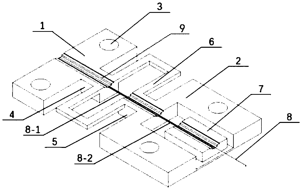
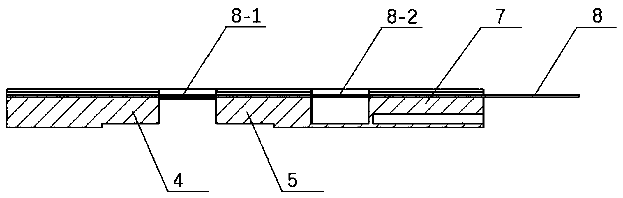
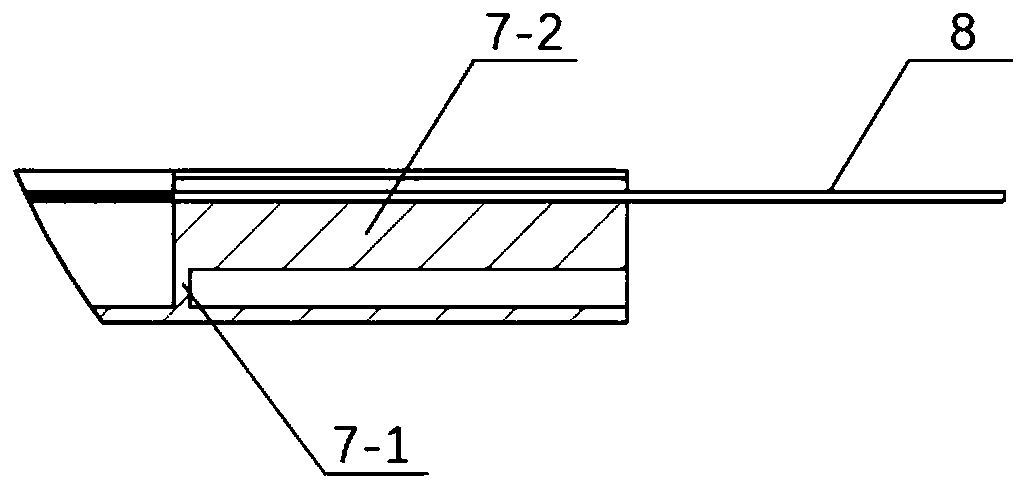
[0030] The structural principle and working principle of the present invention will be described in detail below with reference to the accompanying drawings.

[0031] see Figure 1 to Figure 3 , a fiber grating temperature / vibration / strain composite sensor, comprising a first base 1 and a second base 2 arranged at the same level, the two sides of the first base 1 and the second base 2 are provided with through Hole 3, the opposite ends of the first base 1 and the second base 2 are respectively provided with a first support beam 4 and a second support beam 5, and a spring beam 6 is connected between the first support beam 4 and the second support beam 5 ; The center of the second base 2 is provided with an L-cantilever beam 7, and the center of the top of the L-cantilever beam 7, the first support beam 4, the second support beam 5, the first base 1 and the second base 2 is provided with a groove 9. The optical fiber 8 is pasted in the center of the groove 9, and the suspended ...


PUM


Abstract

A fiber bragg grating temperature / vibration / strain composite sensor and a working method thereof are provided. The fiber bragg grating temperature / vibration / strain composite sensor comprises a first base and a second base, the opposite ends of the first base and the second base are respectively provided with a first supporting beam and a second supporting beam, and a spring beam is arranged between the first supporting beam and the second supporting beam. An L-cantilever beam is arranged in the center of the second base, an optical fiber is pasted in a groove in the top of the sensor, and a first fiber grating and a second fiber grating are separately engraved in the suspended position of the optical fiber. When the vibration is measured, the L-cantilever beam generates the forced vibration and acts on the second fiber bragg grating, and the vibration and temperature signals are obtained by performing fast Fourier transform on the output signal of the second fiber bragg grating; and when the strain is measured, the first fiber bragg grating is compressed or stretched under the action of the strain, and the output signal of the first fiber bragg grating is measured to obtain a strain signal, and meanwhile, the temperature measured by the fiber bragg grating is used for performing temperature compensation on the strain signal. The sensor has the advantages of being simple in structure and high in sensitivity and measurement precision, and being practical and efficient.

Description

technical field [0001] The invention relates to a compound sensor, in particular to a fiber grating temperature / vibration / strain compound sensor and its working method. Background technique [0002] As an optical sensor, fiber optic sensor is widely used in the measurement of physical quantities, such as the measurement of physical and chemical parameters such as temperature, vibration, stress, strain, pressure and concentration of chemical solvents. Optical fiber sensors have the advantages of high sensitivity, anti-electromagnetic interference, and anti-corrosion. In addition, as a kind of fiber optic sensor, fiber grating also has the advantages of small size, light weight, slender and soft, easy to make a simple sensor structure, easy to realize distributed measurement, etc., and has important applications in many engineering fields . [0003] Taking large-scale energy systems as an example, there are often factors such as large temperature differences and strong inter...

Claims


Application Information

Patent Timeline
Patent Type & Authority Applications(China)
IPC IPC(8): G01B11/16G01H9/00G01K1/14G01K11/32G01D3/036G01K11/3206
CPCG01B11/18G01H9/004G01K11/32G01K1/14G01D3/036
Inventor 林启敬姚坤蒋庄德赵娜田边毛琦韩枫赵立波
Owner XI AN JIAOTONG UNIV
Why Eureka
Try Eureka