
Array substrate, display panel and manufacturing method of array substrate

A technology for array substrates and manufacturing methods, which is applied in the display field and can solve problems affecting product quality, cracks in passivation layers, and thin-film transistor devices that cannot realize normal charging and discharging of pixels, etc.

Active Publication Date: 2020-08-07
成都京东方显示科技有限公司
View PDF13 Cites 2 Cited by
  • Summary
  • Abstract
  • Description
  • Claims
  • Application Information

AI Technical Summary

Problems solved by technology

[0004] However, in the above-mentioned passivation layer, due to the characteristics of the material of the silicon-based inorganic insulating layer itself, cracks will appear in the passivation layer. In the subsequent process of etching the transparent conductive film out of the pixel electrode, the etching solution It will follow the cracks in the above-mentioned passivation layer and enter into the semiconductor pattern for etching, which will cause the thin film transistor device to fail to realize the normal charge and discharge of the pixel, thus affecting the quality of the product

Method used


Image

  • Array substrate, display panel and manufacturing method of array substrate
  • Array substrate, display panel and manufacturing method of array substrate
  • Array substrate, display panel and manufacturing method of array substrate

Examples


Embodiment 1

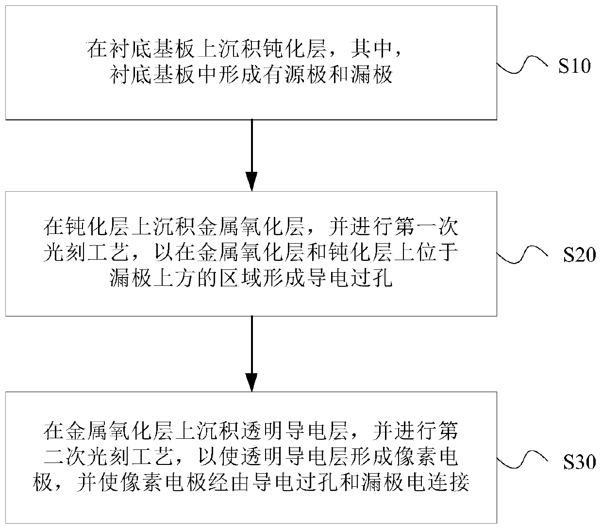
[0038] figure 1 It is a schematic flow chart of the manufacturing method of the array substrate provided by Embodiment 1 of the present invention.

[0039] In the embodiment of the present application, the thin film transistors in the array substrate may be top-gate or bottom-gate thin film transistors, and in the thin film transistors, the semiconductor pattern may be a metal oxide semiconductor pattern or a low temperature polysilicon semiconductor pattern. In other words, in the array substrate in this application, the thin film transistors can be of various types and formation methods, as long as a passivation layer and pixel electrodes are formed on the substrate substrate, the technical solutions in this application can be used to solve the problems in the passivation layer. There is a problem that cracks cause over-etching of the semiconductor layer.

[0040] refer to figure 1 , the manufacturing method of the array substrate of the present invention comprises:

[0041...

Embodiment 2

[0078] This embodiment provides an array substrate 100, which is manufactured by the manufacturing method described in Embodiment 1. Figure 10 A schematic structural diagram of the array substrate 100 provided in Embodiment 2 of the present invention.

[0079] refer to Figure 10 , the array substrate 100 includes: a base substrate 10 and a passivation layer 20, a metal oxide layer 30, and a pixel electrode 50 sequentially formed on the base substrate 10, and a The conductive via hole 31 , the conductive via hole 31 penetrates the passivation layer 20 and the metal oxide layer 30 , and the pixel electrode 50 is electrically connected to the drain electrode 16 through the conductive via hole 31 .

[0080] In the above solution, a layer of metal oxide layer 30 is formed on the passivation layer 20 as a strengthening layer of the passivation layer 20, which can prevent the chemical solution for etching the pixel electrode 50 from penetrating into the semiconductor layer, and av...

Embodiment 3

[0095] This embodiment provides a display panel, including the array substrate 100 in the second embodiment, wherein the specific structure and functions of the array substrate 100 have been described in detail in the second embodiment above, and thus will not be repeated here.

[0096] The display panel may be a liquid crystal display panel. In this case, the display panel includes a color filter substrate, a liquid crystal layer, and the array substrate 100 described in Embodiment 2, and the liquid crystal layer is interposed between the color filter substrate and the array substrate 100 .

[0097] The display panel may also be an organic light emitting diode display panel. In this case, the display panel includes the array substrate 100 described in Embodiment 2, an encapsulation layer and an organic layer, wherein the organic layer is interposed between the array substrate 100 and the encapsulation layer.


PUM


Abstract

The invention provides an array substrate, a display panel and a manufacturing method of the array substrate. The manufacturing method of the array substrate comprises the steps of depositing a passivation layer on a substrate, wherein a source electrode and a drain electrode are formed in the substrate; depositing a metal oxide layer on the passivation layer, and performing a first photoetching process to form a conductive via hole in the metal oxide layer and an area above the drain electrode on the passivation layer, wherein the conductive via hole penetrates through the metal oxide layer and the passivation layer; and depositing a transparent conductive layer on the metal oxide layer, performing a second photoetching process to enable the transparent conductive layer to form a pixel electrode, and enabling the pixel electrode to be electrically connected with the drain electrode through the conductive via hole. According to the invention, cracks in the passivation layer can be avoided, the damage of etching liquid of the pixel electrode to a semiconductor layer is prevented, and the quality of the array substrate is improved.

Description

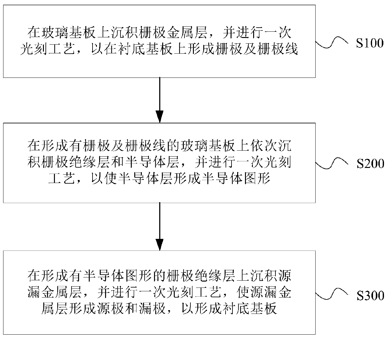
technical field [0001] The present invention relates to the field of display technology, in particular to an array substrate, a display panel and a method for manufacturing the array substrate. Background technique [0002] With the development of display technology, flat display devices such as liquid crystal displays (LCD) are widely used in mobile phones, televisions, personal In various consumer electronic products such as digital assistants and notebook computers, it has become the mainstream of display devices. A liquid crystal display panel is generally composed of an array substrate, a color filter substrate, and a liquid crystal molecular layer sandwiched between the array substrate and the color filter substrate. [0003] In the manufacturing process of the existing array substrate, after forming the gate electrode, the gate insulating layer and the semiconductor pattern on the glass substrate, the source and drain metal layers are deposited on the semiconductor p...

Claims


Application Information

Patent Timeline
IPC IPC(8): H01L21/77H01L27/12H01L27/32G02F1/1362
CPCH01L27/1259H01L27/1248H01L21/77G02F1/1362G02F1/136227H01L2021/775H10K59/123H10K59/12
Inventor 朱成顺李广圣蒋雷
Owner 成都京东方显示科技有限公司
Learn More