A battery module and its gluing equipment and process

A battery module and glue coating technology, which is applied to secondary batteries, coatings, circuits, etc., can solve the problems of certain mechanical strength requirements for modules and liquid-cooled plates, difficulty in discharging air bubbles, difficulty in automation, etc., and achieve good results The effect of electrical insulation properties, low contact thermal resistance, and good heat dissipation effect

Active Publication Date: 2022-05-17
厦门通测电子有限公司
View PDF10 Cites 0 Cited by
  • Summary
  • Abstract
  • Description
  • Claims
  • Application Information

AI Technical Summary

Problems solved by technology

[0004] For liquid-cooled battery packs, the current design method has the following three problems: 1) The heat conduction pad between the module and the liquid-cooled plate has a certain hardness and elasticity, and a certain pressure is required to ensure the stability of the module and the liquid-cooled plate. The heat transfer mating surface between them has certain requirements for the mechanical strength of the module and the liquid cooling plate; 2) The hardness of the heat conduction pad is around shone 00 55, which is soft and easy to deform, and it is difficult to automate in the battery pack assembly process; 3) During the application process of the heat conduction pad, it is easy to form uncertain and difficult-to-discharge air bubbles between the module and the heat conduction pad, the liquid cooling plate and the heat conduction pad, which affects heat transfer
[0005] For the air-cooled battery pack, there are two problems in the current design method: 1) The hardness of the heat conduction pad is about 55 at shone00, which is soft and easy to deform, and it is difficult to automate the battery pack assembly process; , it is easy to form air bubbles that are difficult to discharge between the module and the thermal pad, the box and the thermal pad, and affect the heat transfer

Method used


Image

  • A battery module and its gluing equipment and process
  • A battery module and its gluing equipment and process
  • A battery module and its gluing equipment and process

Examples


Embodiment Construction

[0055] In order to make the technical problems, technical solutions and beneficial effects to be solved by the present invention clearer and clearer, the present invention will be further described in detail below in conjunction with the accompanying drawings and embodiments.

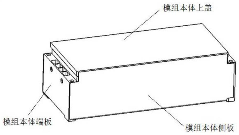
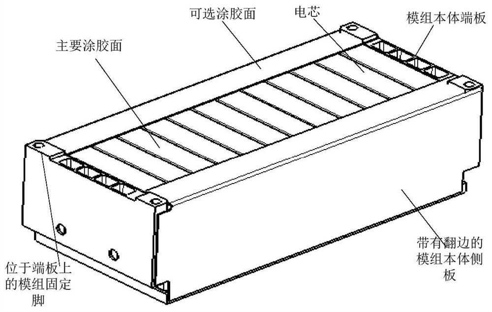
[0056] Such as Figure 1~4 As shown, a battery module includes a module body, and the module body includes a cell arrangement composed of several cells, a module body upper cover, a module body end plate, a module body side plate, and a module signal acquisition The side plate of the module body has a flange facing the battery; optionally, the module body can also include a module bottom plate, and the module bottom plate is located at the bottom of the battery cell arrangement;

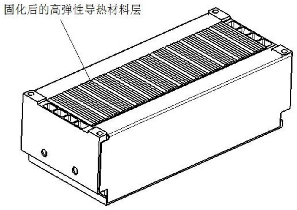
[0057] In this example, the external heat transfer surface of the module body is coated with a layer of highly elastic heat-conducting material; the main external heat transfer surface of the battery module is for the liquid-c...


PUM


Abstract

A battery module and its gluing equipment and process. The battery module includes a module body, and the external heat transfer surface of the module body is coated with a layer of high-elastic heat-conducting material. The gluing process includes two ways of controlling the solenoid valve and controlling the stepping motor. The way to control the solenoid valve is to control the extrusion speed of the glue by adjusting the opening of the valve; the way to control the stepping motor is to control the moving speed of the glue head. Control the glue extrusion speed; the glue application equipment includes a detection system, a glue system, a constant temperature system and a computer terminal; the glue system includes a glue extrusion device and a movement mechanism that controls the extrusion device; It is used to receive the signal from the computer terminal and adjust the opening of the valve; the movement mechanism is controlled by a stepper motor, and the stepper motor receives the signal from the computer terminal to control the moving speed of the movement mechanism. Achieve higher production efficiency and lower process cost than sticking thermal pads, and prevent air bubbles on the mating surface.

Description

technical field [0001] The invention relates to the field of battery modules, in particular to a battery module and its gluing equipment and process. Background technique [0002] During the charging and discharging process of the battery pack, the battery module will heat up; especially in summer, for the liquid-cooled battery pack, the heat generated by the battery module is mainly taken away by the cooling plate; for the natural cooling battery pack, the battery module The heat loss generated is mainly conducted to the battery case through the heat conducting structure, and then dissipated by the battery case into the atmosphere. The battery module is composed of several battery cells side by side. Due to the position tolerance between the battery cells during the module assembly process, the bottom of the module is uneven. If the battery module is directly installed in the battery pack, it will affect the heat transfer and cause The battery temperature is high and the t...

Claims


Application Information

Patent Timeline
Patent Type & Authority Patents(China)
IPC IPC(8): H01M10/613H01M10/6551B05C9/14B05C11/10B05D3/02
CPCH01M10/613H01M10/6551B05C11/1005B05C11/1021B05C9/14B05D3/0254Y02E60/10
Inventor 黄双茂
Owner 厦门通测电子有限公司
Why Eureka
Try Eureka