Legged robot for stable operation in amphibious environment

A robotic and stable technology, applied in amphibious vehicles, motor vehicles, transportation and packaging, etc., can solve the problems of increased volume, weight, system complexity, instability of the body, and heavy motor load, and achieves reduced subsidence depth and use. The effect of long life and simple structure

Active Publication Date: 2021-04-09
HARBIN ENG UNIV
View PDF11 Cites 0 Cited by
  • Summary
  • Abstract
  • Description
  • Claims
  • Application Information

AI Technical Summary

Problems solved by technology

[0003] In the process of realizing the present invention, the inventors found that there are at least the following problems in the prior art: there are two kinds of structures for the legs of common legged robots at present, one is to use multiple motors as joint drive sources, such as the application number 201310273443.3 The Chinese patent discloses a multi-legged mobile device based on a hybrid drive mechanism, which uses multiple motors as the drive source for the joints. Since multiple motors will increase their own volume, weight and system complexity, the motors adjust the forward rotation state and reverse rotation. In the state, the energy consumption is large
The other is to use a multi-link mechanism and use a single drive to complete the movement of the robot's foot. The advantage of this method is that the movement can be completed with a single drive, the overall structure is lighter, and the energy utilization rate is higher. The disadvantage is that the trajectory is mostly fixed. Moreover, the toe trajectory in the support phase is not a straight line, which leads to the instability of the robot body during the movement process, and the weight of the body is borne by fewer motors, and the burden on the motors is generally larger; and the range of activities of the above two footed robots is limited to land , it is difficult to apply to the amphibious environment with complex terrain and luxuriant aquatic organisms

Method used


Image

  • Legged robot for stable operation in amphibious environment
  • Legged robot for stable operation in amphibious environment
  • Legged robot for stable operation in amphibious environment

Examples


Embodiment Construction

[0027] The technical solutions in the embodiments of the present invention will be clearly and completely described below in conjunction with the embodiments of the present invention. Apparently, the described embodiments are only some of the embodiments of the present invention, not all of them. Based on the embodiments of the present invention, all other embodiments obtained by persons of ordinary skill in the art without making creative efforts belong to the protection scope of the present invention.

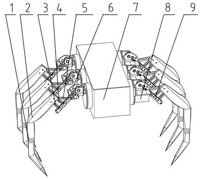
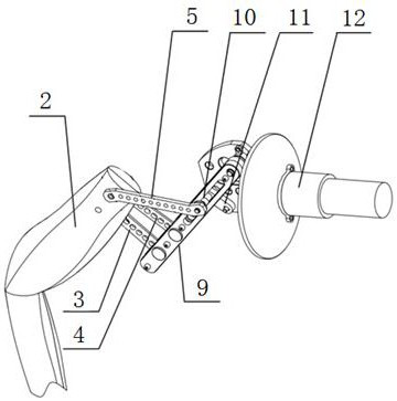
[0028] The legged robot that works stably under the amphibious environment of the embodiment of the present invention, such as Figure 1-2 As shown, it includes a sealed body 7, the body 7 is a waterproof airtight cabin, and the motor 12 is installed in the airtight cabin, which is convenient to work in an amphibious environment. The output shaft is fixedly connected to one end of the crank 11 through the bevel gearbox 8, and the other end of the crank 11 is connected to the ...


PUM


Abstract

The invention discloses a legged robot for stable operation in an amphibious environment, which comprises a sealed body, a motor installed in the body, an output shaft of the motor protruding from the side wall of the body in the form of a dynamic seal, and the output shaft of the motor passes through a bevel gear box It is fixedly connected with one end of the crank, and the other end of the crank is hinged with the slider. The slider is installed in the chute of the guide rod, and the upper end of the guide rod is installed on the body through a bearing. The walls are perpendicular to each other in space; one end of the No. 1 connecting rod is hinged with the slider, the other end of the No. 1 connecting rod is hinged with the root of the leg member, one end of the No. 2 and No. The other ends of the connecting rod and the No. 3 connecting rod are all connected with the roots of the leg members, forming a partially double rocker mechanism. The invention has the advantages of simple structure, easy maintenance, high energy utilization rate, fast and stable movement, self-locking ability, strong bearing capacity, convenient modular mass production, and amphibious operation ability.

Description

technical field [0001] The invention belongs to the technical field of legged robots, and relates to a legged robot that operates stably in an amphibious environment. Background technique [0002] Multi-legged robots generally refer to robots with four or more legs. Compared with wheeled and tracked robots, they have stronger motion flexibility. The environment has strong adaptability, can walk stably in complex and harsh unstructured environments, and can replace manual work, so it has strong practical value. [0003] In the process of realizing the present invention, the inventors found that there are at least the following problems in the prior art: there are two kinds of structures for the legs of common legged robots, one is to use multiple motors as joint drive sources, such as the application number 201310273443.3 A Chinese patent discloses a multi-legged mobile device based on a hybrid drive mechanism, which uses multiple motors as the drive source for the joints. S...

Claims


Application Information

Patent Timeline
Patent Type & Authority Patents(China)
IPC IPC(8): B62D57/032B60F3/00
CPCB60F3/0007B62D57/032
Inventor 王立权马鑫盟王刚贾鹏
Owner HARBIN ENG UNIV
Why Eureka
Try Eureka