Ultralow-loss large-mode-field optical fiber side pumping beam combiner and manufacturing method thereof

A technology of side pumping and manufacturing method, applied in the field of optical fiber, can solve the problems of reducing the quality of the output beam of the laser, reducing the performance and reliability of the whole machine, and increasing the loss of the fundamental mode signal, so as to improve the industrial production efficiency and improve the overall performance. , Improve the effect of signal output power

Pending Publication Date: 2020-08-11
INNO LASER TECH CORP LTD
View PDF14 Cites 0 Cited by
  • Summary
  • Abstract
  • Description
  • Claims
  • Application Information

AI Technical Summary

Problems solved by technology

[0010] In the current industrial application, the core diameter of the large mode field fiber is generally 10-30um, and the small deformation caused by the above factors can easily reach more than 10um, which has obvious effects on the shape structure, coaxiality and symmetry of the core diameter. The injected fundamental mode signal will be excited into a higher-order mode after passing through the melting zone, resulting in greater loss of the fundamental mode signal
[0011] The large loss of the fiber optic device will cause the laser to require higher pumping power to achieve the same power output, which will introduce more noise, thereby reducing the performance and reliability of the whole machine, and at the same time, the distorted high-order mode will also reduce the power of the laser. The output beam quality of

Method used


Image

  • Ultralow-loss large-mode-field optical fiber side pumping beam combiner and manufacturing method thereof
  • Ultralow-loss large-mode-field optical fiber side pumping beam combiner and manufacturing method thereof
  • Ultralow-loss large-mode-field optical fiber side pumping beam combiner and manufacturing method thereof

Examples


Embodiment

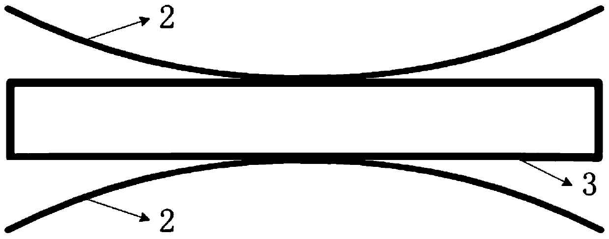
[0045] Such as image 3As shown, this embodiment takes the manufacture of an ultra-low loss large-mode-field fiber side-pumped beam combiner as an example to illustrate that the large-mode-field fiber can be thinned during the melting process to achieve a beam combiner with very small fundamental mode loss ; specifically including two pumping fibers 2 and a large-mode-field signal fiber 3, wherein the model of the pumping fiber is 105 / 125 0.22NA, and the model of the large-mode-field signal fiber is 25 / 250 0.07 / 0.46NA. The pump fiber is thinned and attached to the surface of the large-mode-field signal fiber, and then melted together, so that the pump light can be coupled to the cladding of the large-mode-field signal fiber for transmission. The specific manufacturing process includes the following steps:

[0046] a. Prepare the oxyhydrogen flame tapering machine and the fixtures corresponding to the above-mentioned fiber types, and then use the thermal stripping method or cor...


PUM


Abstract

The invention discloses an ultralow-loss large-mode-field optical fiber side pumping beam combiner and a manufacturing method thereof, and the method comprises the following steps: removing a coatinglayer, corresponding to a fusion combination part, in a large-mode-field signal optical fiber and a pumping optical fiber, and exposing an internal cladding layer; attaching the exposed cladding layers in the two pumping optical fibers tightly to the two sides of the cladding layer in the large-mode-field signal optical fiber respectively to form an optical fiber bundle; then melting and heating acladding region in the optical fiber bundle; when the optical fiber bundle is heated to a molten state, stretching the optical fiber bundle, so that the size of a molten area in the large-mode-fieldsignal optical fiber is thinned and reduced to form a conical structure with two symmetrical ends, then recovering the optical fiber bundle to the room temperature to form a solid state, and welding the large-mode-field signal optical fiber and the pumping optical fiber into a whole. According to the invention, the optical fiber is properly thinned in the fusion sintering process, and tiny deformation of a machine, a clamp, gravity and thermal stress factors on the large-mode-field signal optical fiber is weakened, so that the degree of distortion of a fundamental mode signal when the fundamental mode signal passes through a fusion sintering area is very small.

Description

technical field [0001] The invention belongs to the field of optical fiber technology, and in particular relates to an ultra-low loss large-mode-field optical fiber side-pumped beam combiner and a manufacturing method thereof. Background technique [0002] High-power fiber lasers have been widely used in industrial processing, medical treatment, national defense and military and other fields. In fiber lasers, the performance of high-power fiber devices is particularly important. Due to the large core diameter area of ​​the large mode field fiber, the threshold of nonlinear effects (SPM, SBS, SRS, etc.) can be increased, so as to ensure that the pulse width and spectral width of the signal light are not changed. Therefore, large mode field fibers are suitable for high average power transmission and have been widely used in the field of high-power fiber lasers. [0003] There is a very important parameter in fiber design: normalized frequency (V parameter), to measure the nu...

Claims


Application Information

Patent Timeline
IPC IPC(8): G02B6/245G02B6/255H01S3/067H01S3/094
CPCG02B6/245G02B6/2551H01S3/06729H01S3/094019H01S3/094053
Inventor 熊波波邹达
Owner INNO LASER TECH CORP LTD
Why Eureka
Try Eureka