All-vertical double-rod type optical element positioning and adjusting device

An optical element, positioning adjustment technology, applied in optical elements, optics, installation, etc., can solve problems such as the inability to directly set the micron-level precision adjustment mechanism, reduce the improvement of the accuracy of the optical system, and the optical optical path is not stable enough. Precise adjustment operation, easy installation and disassembly, and easy integration of components

Active Publication Date: 2020-08-11
SHANXI UNIV
View PDF5 Cites 3 Cited by
  • Summary
  • Abstract
  • Description
  • Claims
  • Application Information

AI Technical Summary

Problems solved by technology

Although this type of optical element fixed installation adjustment assembly can accurately fix the relative position of the optical element, the disassembly and assembly are complicated. When it is necessary to replace a fixed plate assembly in the constructed system, it is necessary to disassemble most of the components in the same direction as the steel fixed rod. , which greatly increases the difficulty of reconstruction of the optical device, which is not conducive to the repeatability of the phenomenon in the optical system that requires extremely high accuracy of the relative position
It is also worth noting that d

Method used


Image

  • All-vertical double-rod type optical element positioning and adjusting device
  • All-vertical double-rod type optical element positioning and adjusting device
  • All-vertical double-rod type optical element positioning and adjusting device

Examples


Example Embodiment

[0042] In order to make the objectives, technical solutions, and advantages of the embodiments of the present invention clearer, the technical solutions in the embodiments of the present invention will be described clearly and completely below. Obviously, the described embodiments are part of the embodiments of the present invention, not All the embodiments; based on the embodiments of the present invention, all other embodiments obtained by those of ordinary skill in the art without creative work shall fall within the protection scope of the present invention.

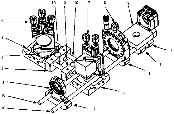
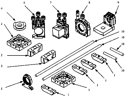
[0043] Such as Figure 1~2 As shown, the first embodiment of the present invention provides a full-vertical double-rod optical element positioning adjustment device, which includes an optical element positioning assembly and an optical element adjustment assembly; the optical element positioning assembly includes: a bottom fixing member 1, an adapter Fixing part 2, square fixing part 3, rigid support rod 10.

[0044] Such ...


PUM


Abstract

The invention belongs to the field of optical devices, and discloses an all-vertical double-rod type optical element positioning and adjusting device. The device comprises an optical element positioning assembly and an optical element adjusting assembly. The optical element positioning assembly comprises a bottom fixing piece, a switching fixing piece, a square fixing piece and a rigid supportingrod, wherein the upper surface of the bottom fixing piece and the upper surface of the square fixing piece in the first direction are each provided with two first cylindrical surface grooves used forbeing matched with the rigid supporting rod; the switching fixing piece is provided with a connecting hole used for being connected with the square fixing piece and two rod holes matched with the sections of the rigid supporting rods; two second cylindrical surface grooves used for being matched with the rigid supporting rod are formed in the bottom of the optical element adjusting assembly, the optical element adjusting assembly is fixedly connected with the bottom fixing piece or the square fixing piece through screws, and the second cylindrical surface grooves in the optical element adjusting assembly are used for being matched with the rigid supporting rod. The device is compact in structure, convenient to adjust and reasonable in design.

Description

technical field [0001] The invention belongs to the field of optical devices, and in particular relates to a full vertical double-rod optical element positioning adjustment device. Background technique [0002] With the rapid development of quantum optics, optogenetics, and optical communication, the use of coherent and incoherent light for optical imaging, optical sensing, and spectral analysis has become a necessary supporting force for industrial groups and scientific research institutes. The development of this series of precision technologies is inseparable from high-quality optical components and corresponding fixed installation adjustment components. Stable and efficient optical element positioning adjustment components can greatly help and promote the improvement and development of related industrial technologies. [0003] Usually, the optical element positioning adjustment assembly needs to achieve stable fixation, fine adjustment and even quick replacement when up...

Claims


Application Information

Patent Timeline
IPC IPC(8): G02B6/32G02B6/34G02B7/18
CPCG02B7/1805G02B6/32G02B6/34
Inventor 元晋鹏董世超汪丽蓉
Owner SHANXI UNIV
Why Eureka
Try Eureka