A Construction Method for Bottom Expansion Pile with Pressure Grouting Concrete with Long Helical Drilling

A long-spiral drilling and concrete pouring technology, which is applied to drilling equipment and methods, drill pipes, drill pipes, etc. problems, to achieve the effect of ensuring bearing capacity, ensuring stability, and avoiding excessively large apertures

Active Publication Date: 2021-08-10
江西中恒地下空间科技有限公司
View PDF1 Cites 0 Cited by
  • Summary
  • Abstract
  • Description
  • Claims
  • Application Information

AI Technical Summary

Problems solved by technology

[0013] The above existing technical solutions have the following defects: during the drilling process of the helical blade, the soil generated in the hole will be discharged out of the pile hole along with the guidance of the helical blade, but during the drilling construction process of the bottom hole, The soil dropped from the wall of the reamed hole will be outside the spiral blade, and part of the soil cannot be discharged out of the hole with the helical blade, so that the soil will fall on the bottom wall of the reamed hole. One way is to pull the drill pipe out of the pile hole Finally, the pumping method is used to remove the dregs at the bottom of the hole; however, the salary of the existing construction personnel is generally settled according to the amount of the pile foundation, and because the auger drill pipe is used to remove most of the soil, there are most construction personnel , when the auger drill pipe is used for construction, it will not waste time to use the pumping method alone to clean the bottom of the hole; in turn, in the process of subsequent pipe pile construction, there is a soft soil layer between the bottom of the pile foundation and the bottom expansion hole, which reduces the expansion. The stable connection between the bottom pile and the soil will affect the bearing capacity of the bottom pile to a certain extent

Method used


Image

  • A Construction Method for Bottom Expansion Pile with Pressure Grouting Concrete with Long Helical Drilling
  • A Construction Method for Bottom Expansion Pile with Pressure Grouting Concrete with Long Helical Drilling
  • A Construction Method for Bottom Expansion Pile with Pressure Grouting Concrete with Long Helical Drilling

Examples


Embodiment Construction

[0058] The present invention will be described in further detail below in conjunction with the accompanying drawings.

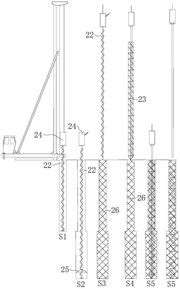
[0059] refer to figure 1 , is a kind of long helical drilling press grouting concrete bottom expansion pile construction method disclosed by the present invention, and its steps are as follows:

[0060] S1, the long screw pile driver is in place, the upper part of the drill pipe 22 is connected with the power head 24, the lower part of the drill pipe 22 is connected with the bottom expansion drill bit 25, and the bottom expansion drill bit 25 is kept closed, and the hole is drilled downward at the predetermined pile position, and continues to drill until The layer where bottom expansion construction is expected to be carried out;

[0061] S2, drill to the pile diameter above the designed pile bottom level, slow down the rotating speed of the drill pipe 22, and at the same time expand the bottom expansion drill bit 25 gradually, and carry out the hole reaming...


PUM


Abstract

The present invention involves a long spiral drilling rhombus pressure irrigation concrete expansion bottom pile construction method. It belongs to the technical field of pile foundation construction. The steps are as follows: S1, direct holes; S2, expansion drills to expand construction piles to expand the head; S3,, S3,, S3, S3, After the drill rod and the bottom drill, the bottom of the pile hole is irrigated and irrigated the concrete, and after the pouring part of the expansion hole is poured, the bottom and lower position of the drilling bits are shifted to rehabilitate the concrete expansion hole. Diamond, and continue to irrigate concrete in the pile holes until the drill is lifted to the ground; S5, use the vibrator to place the steel cage towards the pile hole; S6. After the pile is fired, it is maintained and inspected. The present invention has a convenient construction, enhances the stability between the bottom piles and the soil, and ensures the effect of the loading capacity of the bottom pile.

Description

technical field [0001] The invention relates to the technical field of pile foundation construction, in particular to a construction method for a long auger drilled press-grown concrete bottom expansion pile. Background technique [0002] At present, the expanded bottom pile is a cast-in-situ pile whose bottom diameter is greater than the upper pile body diameter. The bearing capacity of a single pile is much higher than that of a straight pile with the same diameter of the pile body. The construction process is generally as follows: S1: Hole forming, using the drill bit to drill vertically; S2: Bottom expansion, after the hole reaches the design elevation, lift the drill bit, replace the reaming bit, and put the reaming bit into the bottom of the hole , to drive the reaming drill bit to expand, the drill pipe to rotate, and the drill bit to cut the hole wall until the designed hole diameter; S3: Clear the hole, discharge the sediment in the hole; S4: Form a pile, first pou...

Claims


Application Information

Patent Timeline
Patent Type & Authority Patents(China)
IPC IPC(8): E02D5/34E21B7/28E21B10/32E21B10/62E21B17/22
CPCE02D5/34E21B7/28E21B10/322E21B10/62E21B17/22
Inventor 曹开伟刘建文聂恺冯上涛罗鹏姚时
Owner 江西中恒地下空间科技有限公司
Why Eureka
Try Eureka