
Control method of bypass system of gas-steam combined cycle unit

A combined cycle unit, bypass control technology, applied in non-electric variable control, control/regulation systems, and simultaneous control of multiple variables, etc., can solve the problems of disturbed water level protection action, high steam pressure protection action, and high steam temperature.

Active Publication Date: 2020-08-14
GUODIAN NANJING ELECTRIC POWER TEST RES CO LTD
View PDF6 Cites 11 Cited by
  • Summary
  • Abstract
  • Description
  • Claims
  • Application Information

AI Technical Summary

Problems solved by technology

[0005] a. When the steam turbine trips, the steam pressure of the system rises rapidly, the response time and opening of the bypass valve are not suitable, and the steam pressure of the system fluctuates greatly, which directly leads to the high steam pressure protection action
[0006] b. Steam pressure fluctuations directly affect the stability of the water level of the boiler drum, and large disturbances cause water level protection actions
[0007] c. Improper response time and flow control of the bypass desuperheating water, resulting in too high or too low steam temperature behind the bypass valve, high temperature bypass valve closed, boiler protection action interlock gas turbine trip
If the temperature is too low, the water in the pipeline behind the valve will cause water hammer, causing major safety accidents in pipeline equipment

Method used


Image

  • Control method of bypass system of gas-steam combined cycle unit
  • Control method of bypass system of gas-steam combined cycle unit
  • Control method of bypass system of gas-steam combined cycle unit

Examples


Embodiment Construction

[0033] The present invention will be described in detail below in conjunction with the accompanying drawings and specific embodiments.

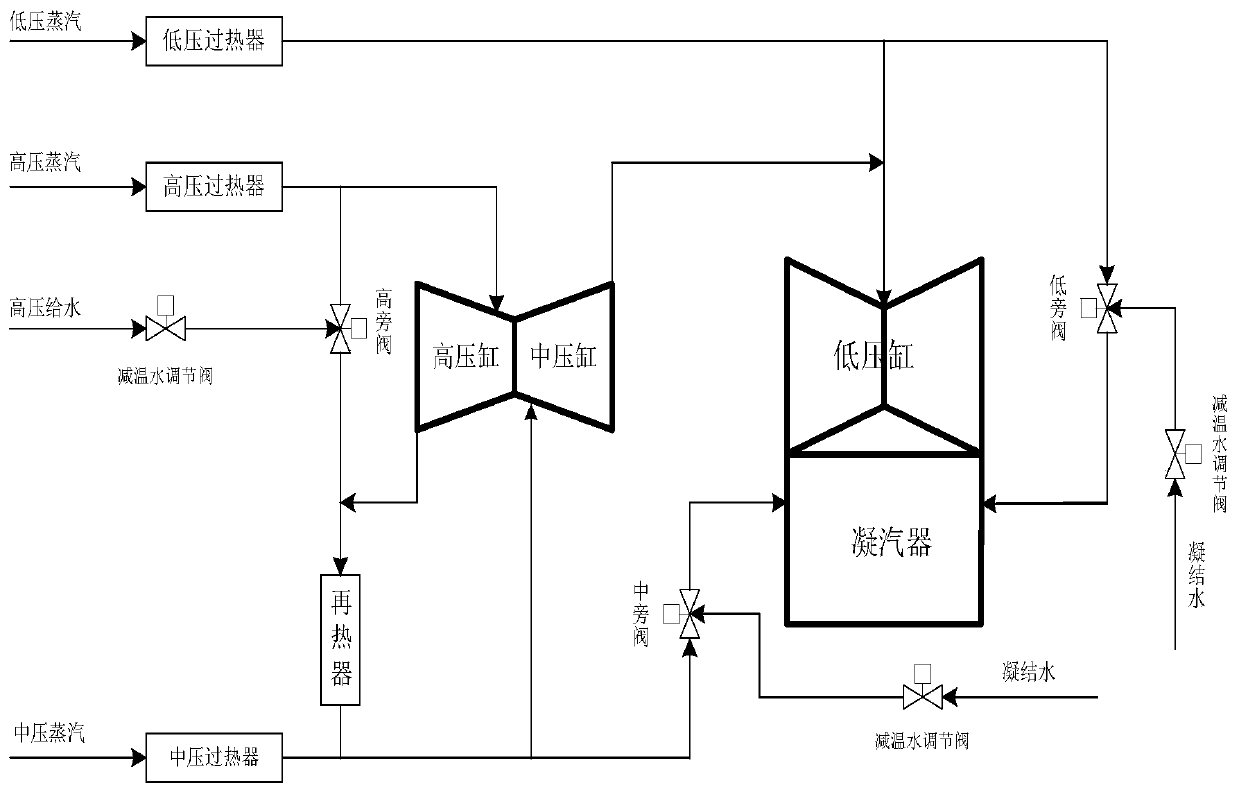
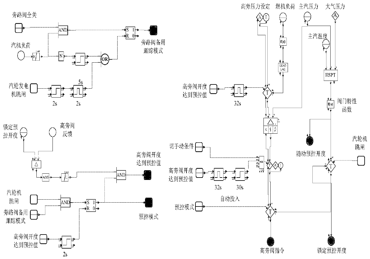
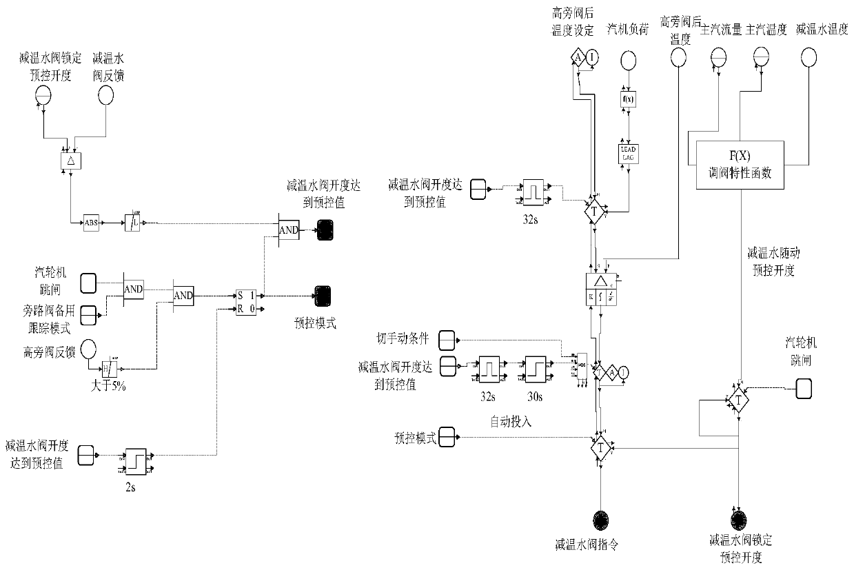
[0034] Such as figure 1 As shown, this embodiment takes the bypass valve system adopted by the combined cycle unit with load distribution of 300MW gas turbine and 140MW steam turbine as an example. In the steam combined cycle working condition, the valve of the steam bypass system is fully closed and is in the tracking standby state. Through special processing of the control logic of the bypass system, after the trip signal of the steam turbine is triggered, the bypass valve immediately implements a quick opening function module. The function module is divided into High, medium and low pressure bypass valves and desuperheating water regulating valves. This precisely calculated control block can effectively control the steam bypass valve system. After the bypass valve is opened and stabilized, it will switch to pressure control mode. The slid...


PUM


Abstract

The invention discloses a control method of a bypass system of a gas-steam combined cycle unit. The control method is characterized in that the operation working condition of a steam turbine is simulated in the whole process, preset opening degrees of valves are dynamically calculated by combining characteristic functions of bypass valves and an energy conservation law, pulse signals of the presetopening degrees of the valves are output at intervals, after a trip signal of the steam turbine is triggered and meets the pulse signals of the preset opening degrees, a valve opening instruction istriggered immediately, and each bypass valve is rapidly opened to the preset opening degrees in response. According to the control method of the bypass system of the gas-steam combined cycle unit, accurate dynamic control of a bypass valve system can be effectively achieved, parameters of a steam system are well stabilized, it is ensured from the technical level that a gas turbine can drive the bypass system to operate independently in case of trip of the steam turbine, system equipment is safe and reliable, and economic loss and social influence caused by malfunction accidents of the gas turbine on a power grid and a power plant are avoided.

Description

technical field [0001] The invention relates to a control method for a bypass system of a gas-steam combined cycle unit, and belongs to the technical field of debugging of a gas-steam combined cycle unit. Background technique [0002] The present invention is aimed at the research carried out on the bypass system of the domestically imported large-scale gas-steam combined cycle unit. The load distribution of this type of combined cycle unit is 300MW gas turbine and 140MW steam turbine. If the protection action of the gas turbine device is activated, the gas turbine system still has the function of independent operation. The steam turbine adopts a double-flow arrangement of high and medium pressure combined cylinders and low pressure cylinders. The steam turbine bypass adopts a high pressure bypass and a medium pressure bypass connected in series. The bypass system device is composed of a bypass valve (including a desuperheater), a water spray regulating valve, a water spray...

Claims


Application Information

Patent Timeline
IPC IPC(8): F01D17/10F01D21/00G05D27/02
CPCF01D17/10F01D17/145F01D21/00G05D27/02
Inventor 林加伍竺有刚于强朱旭初丁阳刚
Owner GUODIAN NANJING ELECTRIC POWER TEST RES CO LTD
Learn More