
Hydrothermal rock breaking cracking device, detonating network and directional cutting method thereof

A technology of detonation network and rock-breaking device, which is applied in blasting, blasting barrels, earthwork drilling and mining, etc. It can solve the problems of easy explosion risk, high pressure, and hidden safety hazards, so as to increase the rock-breaking effect and reduce vibration disturbance and noise , Reduce the effect of rock debris dust

Pending Publication Date: 2020-08-14
江苏中控能源科技有限公司
View PDF1 Cites 6 Cited by
  • Summary
  • Abstract
  • Description
  • Claims
  • Application Information

AI Technical Summary

Problems solved by technology

[0003] However, there are three potential safety hazards in traditional carbon dioxide gas explosion technology. 1) The filling, storage and transportation of liquid carbon dioxide involve high-pressure containers, which are prone to explosion risks; 2) carbon dioxide gas explosion requires the use of flammable and explosive materials. 3) After the carbon dioxide gas explosion device is filled with liquid carbon dioxide, it is easy to generate high pressure. The explosive type of fever medicine is directly placed in the high-pressure liquid carbon dioxide and directly contacted. Gas explosion device presents a risk of explosion

Method used


Image

  • Hydrothermal rock breaking cracking device, detonating network and directional cutting method thereof
  • Hydrothermal rock breaking cracking device, detonating network and directional cutting method thereof
  • Hydrothermal rock breaking cracking device, detonating network and directional cutting method thereof

Examples


Embodiment 1

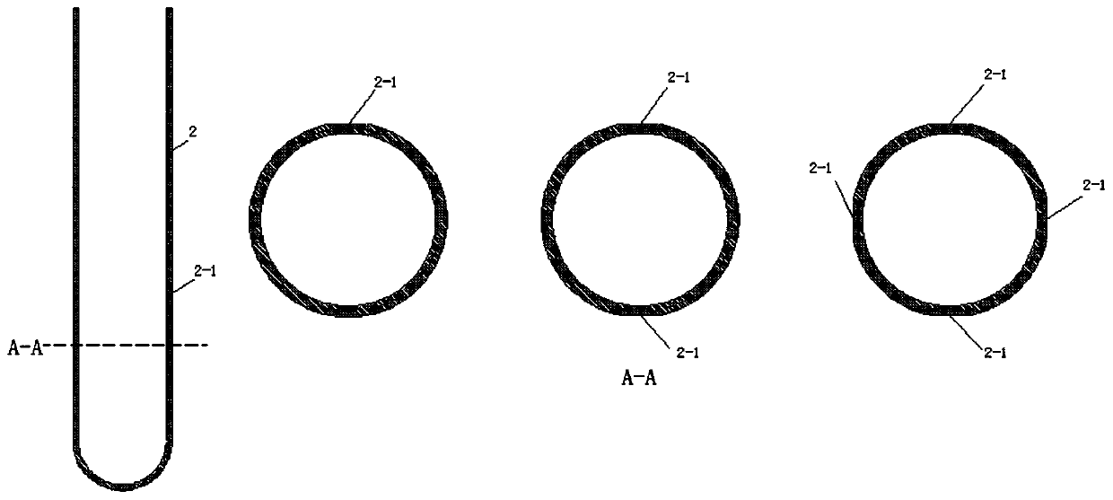
[0038] Such as figure 1 As shown, a hydrothermal rock-breaking fracturing device includes a directional cracker 2, an ionic aqueous solution 11 is housed in the directional cracker 2, an inner liner heat pipe 3 is fixed inside the directional cracker 2, The liner heat pipe 3 includes a plug 10, a heat insulating component 6 and an energy-gathering agent 4 from top to bottom. Among them, the other end of the resistance wire 5 is connected to an electric wire 9, and the electric wire 9 is connected to an electric exciter, and the electric exciter is connected to a mobile power supply. The connection between the directional cracker 2 and the inner tank heat pipe 3 is provided with a water injection end 7, and the middle and lower end of the directional cracker 2 is provided with a weak gap 2-1. The inner liner heat pipe 3 has good thermal conductivity, and directly transfers the heat released by the combustion of the energy gathering agent 4 to the ion aqueous solution 11, and t...

Embodiment 2

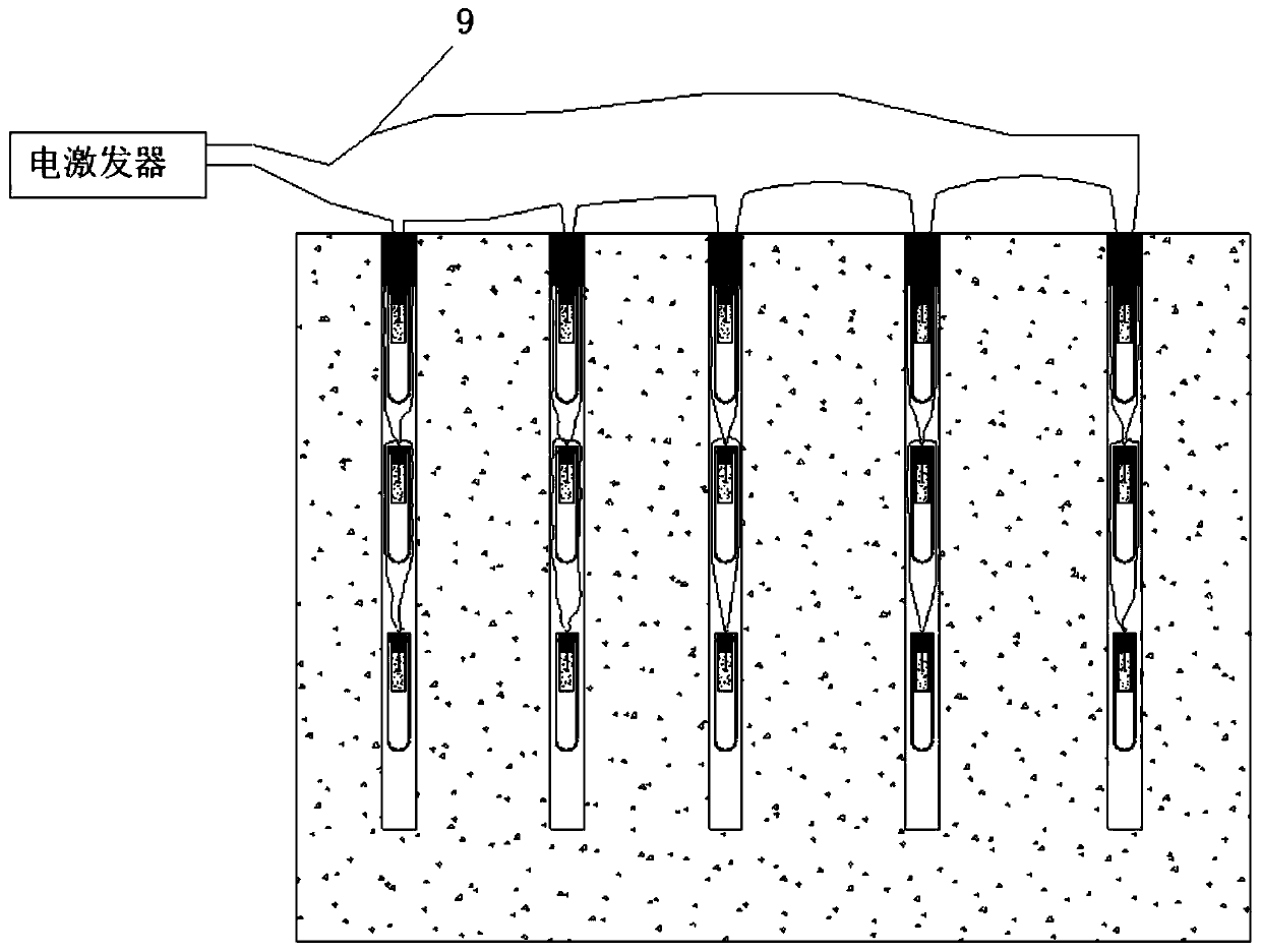
[0043] Such as image 3As shown, a hydrothermal rock-breaking detonation network includes a number of hydrothermal rock-breaking fracturing devices described in Embodiment 1. A single-hole device network formed in parallel, the single-hole device network is placed in a single borehole, Single-hole device nets are placed in different boreholes, and different single-hole device nets are connected in series to form a complex detonation network. The number of hydrothermal rock-breaking fracturing devices connected in series and parallel in the detonation network can be determined according to the actual site survey. For example, 2-3 hydrothermal rock-breaking devices are usually installed in a single borehole, and complex terrain can also be connected in parallel. Multiple hydrothermal rock-breaking and fracturing devices. When connecting in series and parallel, directly connect the electric wire 9 reserved on the hydrothermal rock-breaking fracturing device for series and parall...

Embodiment 3

[0048] A directional cutting method for hydrothermal rock breaking, comprising the following steps:

[0049] S1: Water injection of hydrothermal rock breaking device: inject ionized aqueous solution 11 into directional cracker 2 through water injection port 8, and close water injection port 8 after directional cracker 2 is filled with ionized aqueous solution 11;

[0050] S2: Series-parallel connection of the hydrothermal rock-breaking device: according to the site geological conditions, connect the wires 9 on the hydrothermal rock-breaking device in series and parallel;

[0051] S3: Hole drilling, orientation, and hole sealing: put the series-parallel connected directional crackers 2 into several drill holes, adjust the direction of the weak gap 2-1 of the directional cracker 2 according to the requirements of the directional cutting direction, and seal the holes. hole;

[0052] S4: connect to the detonation network, and detect the connectivity;

[0053] S5: Security alert,...


PUM


Abstract

The invention discloses a hydrothermal rock breaking cracking device, a detonating network and a directional cutting method thereof, and belongs to the field of mine mechanical engineering. The devicecomprises a directional cracker (2). The directional cracker (2) contains an ion water solution (11). The directional cracker (2) is provided with an inner container heat conducting pipe (3). A weakgap (2-1) is formed in the lower middle end of the directional cracker (2). The directional cutting method comprises the following steps that S1, water is injected into hydrothermal rock breaking devices; S2, hydrothermal rock breaking devices are in series-parallel connection; S3, hole forming, orienteering and hole sealing are performed; S4, the detonating network is connected, and the connectivity is detected; S5, security alert is given, and detonation is performed; S6, after one-time directional cutting operation is completed, the steps 1-5 are executed repeatedly, and circulation at thenext stage is started. Hydrothermal rock breaking cracking is adopted for replacing carbon dioxide gas explosion cracking, potential safety hazards in the storage, transporting and using processes aregreatly reduced, meanwhile, vibration disturbance and noise can further be lowered, and the device is particularly applicable to some specific environments where intense vibration and noise are forbidden.

Description

technical field [0001] The invention belongs to the field of mining machinery engineering, and in particular relates to a hydrothermal rock-breaking fracturing device, an initiating network and a directional cutting method thereof. Background technique [0002] In municipal transportation projects such as mining and stone mining, excavation of foundation pits, construction of tunnels and underground spaces, safe blasting and demolition of stubborn rocks / solitary rocks, and dredging of pipelines and other blockages, it is often necessary to excavate rock mass. In order to ensure the safety of surrounding structures and personnel, and reduce rock-breaking vibration and noise, CO 2 Gas explosion technology is being widely concerned in mining, tunneling, municipal transportation and other fields. [0003] However, there are three potential safety hazards in traditional carbon dioxide gas explosion technology. 1) The filling, storage and transportation of liquid carbon dioxide i...

Claims


Application Information

Patent Timeline
IPC IPC(8): F42B3/04F42D1/00F42D3/04E21C37/14
CPCE21C37/14F42B3/04F42D1/00F42D3/04
Inventor 胡少斌季淮君王恩元
Owner 江苏中控能源科技有限公司
Learn More