Magnetoacoustic emission detection method for fatigue damage of ferromagnetic metal component

A technology of acoustic emission detection and metal components, which is applied in the field of non-destructive testing of material damage, can solve the problems of inability to distinguish the stable growth of fatigue cracks, monotonous decline, and inability to distinguish the rapid growth of fatigue cracks in the second stage of stable growth, so as to improve anti-noise The effect of interference ability

Pending Publication Date: 2020-08-14
CHINA SPECIAL EQUIP INSPECTION & RES INST
View PDF12 Cites 3 Cited by
  • Summary
  • Abstract
  • Description
  • Claims
  • Application Information

AI Technical Summary

Problems solved by technology

Hou Binglin et al. (Hou Binglin, Zhou Jianping, Peng Xiang, et al. Application research of magnetoacoustic emission in non-destructive testing of rail properties [J]. Experimental Mechanics, 1998 (01): 99-105), using sine wave voltage signal The U74 rail steel was tested by MAE. The results show that with the increase of the number of fatigue cycles, the root mean square voltage of the MAE signal increases first and then decreases monotonously. It reaches the maximum value at about 20% of the fatigue life, and the greater the magnetic field strength Hmax The above rule is more obvious ( figure 1 ), however, it cannot distinguish the stable growth of the fatigue crack stage I from the rapid growth stage II
Similarly, the inventor of the present application uses the sine wave voltage signal to excite the Q235 steel to obtain the change of the root mean square voltage of the MAE signal with the fatigue cycle, and also draws a similar rule ( figure 2 ), and it is also impossible to distinguish between the two stages of stable growth of fatigue cracks in stage I and rapid growth in stage II

Method used


Image

  • Magnetoacoustic emission detection method for fatigue damage of ferromagnetic metal component
  • Magnetoacoustic emission detection method for fatigue damage of ferromagnetic metal component
  • Magnetoacoustic emission detection method for fatigue damage of ferromagnetic metal component

Examples


Embodiment Construction

[0031] The present invention will be further described below in conjunction with the accompanying drawings and specific embodiments.

[0032] The block diagram of the steps of the detection method of the present invention is shown in image 3 ,Proceed as follows;

[0033] 1) Place the self-made U-shaped electromagnetic yoke and the acoustic emission sensor in the central area of ​​the Q235 steel member without fatigue loading in a relatively fixed position.

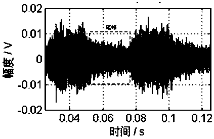
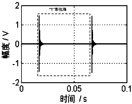
[0034] 2) Load a periodic sine wave voltage signal to the coil of the U-shaped electromagnetic yoke with a frequency of 20 Hz, where the voltage signal is generated by a function generator and amplified 10 times by a power amplifier before being input to the coil. Since the MAE signal is generated under the alternating magnetic field excited by the sine wave voltage signal, the Q235 steel member generates two identical MAE signals within one magnetization period, that is, the frequency of the MAE signal is twice the freq...


PUM


Abstract

The invention relates to a magnetoacoustic emission detection method for fatigue damage of a ferromagnetic metal component. The method comprises the steps of firstly, generating an excitation magneticfield by using a sine wave voltage signal, gradually increasing a loading voltage until a bimodal envelope magnetoacoustic emission signal with an obvious tail peak is obtained, and taking a corresponding voltage peak value as a reference voltage; then, generating an excitation magnetic field by using a square wave voltage signal equal to or higher than a reference voltage, and acquiring a magnetoacoustic emission signal with a T-shaped envelope; and thirdly, calculating the average value of peak-to-peak values of the magnetoacoustic emission signal in multiple periods to serve as a characteristic parameter, and enabling the characteristic parameter to have inflection point change along with the development of the initiation and expansion of the fatigue crack, thereby identifying the initiation and expansion of the fatigue micro-crack, and giving a timely early warning for the failure of the component. According to the invention, the T-shaped envelope signals are obtained through square wave voltage excitation, the waveform of the T-shaped envelope signals is clear and easy to distinguish, on the basis that the reference voltage ensures enough magnetic field intensity, the anti-noise capacity of MAE is greatly improved, MAE fatigue monitoring engineering application is achieved, and the detection result is stable and reliable.

Description

technical field [0001] The invention belongs to the technical field of nondestructive detection of material damage, and in particular relates to a magnetoacoustic emission detection method for fatigue damage of ferromagnetic metal components. Background technique [0002] The fatigue life of metal components subjected to cyclic loading for a long time can be divided into three stages: (1) The first stage is the fatigue hardening or softening stage. In this stage, the microstructure of the material changes as a whole, and finally forms a stress-strain concentration area, resulting in Fatigue damage; (2) The second stage is the crack initiation stage, and the crack length in this stage is usually not greater than the grain size (10μm-100μm); (3) The third stage is the crack propagation stage, which is divided into stage I Stable crack growth and rapid crack growth in the second stage. The stable crack growth in the first stage refers to the expansion of the micro-crack along t...

Claims


Application Information

Patent Timeline
Patent Type & Authority Applications(China)
IPC IPC(8): G01N27/72G01N29/14G01N29/24G01N29/44
CPCG01N27/725G01N29/14G01N29/2412G01N29/44G01N2291/0234G01N2291/0289G01B7/24
Inventor 沈功田沈永娜张文君
Owner CHINA SPECIAL EQUIP INSPECTION & RES INST
Why Eureka
Try Eureka