Cloth waste treatment device for spinning

A technology for processing devices and rags, which is applied to heating devices, grain processing, cleaning methods and utensils, etc., can solve the problems of unsatisfactory processing effects of rags, and achieve the effects of improving crushing effect, convenient processing, and improving processing effect

Inactive Publication Date: 2020-08-18
湖北延昌纺织股份有限公司
View PDF8 Cites 3 Cited by
  • Summary
  • Abstract
  • Description
  • Claims
  • Application Information

AI Technical Summary

Problems solved by technology

It is necessary to use a special textile rag processing device to crush the textile waste, so as to facilitate better recycling of the crushed textiles, but the existing devices

Method used


Image

  • Cloth waste treatment device for spinning
  • Cloth waste treatment device for spinning
  • Cloth waste treatment device for spinning

Examples


Embodiment 1

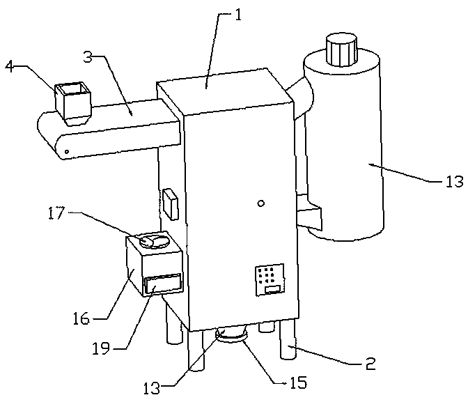
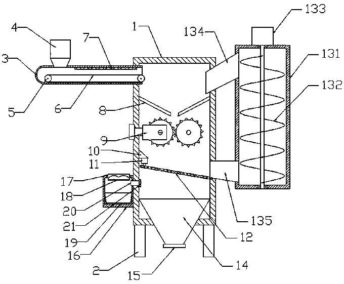
[0022] see Figure 1-3 As shown, the present embodiment is a rag processing device for weaving, comprising an outer shell 1, the four corners of the bottom of the outer shell 1 are connected with columns 2, and the upper left part of the outer shell 1 is connected with a feed channel 3, and the feed channel 3 The left side of the top of the top is connected with a hopper 4, and the left and right ends of the feed channel 3 are connected to the conveyor roller 5, and the conveyor belt 6 is set between the two sets of conveyor rollers 5, and the right end of the conveyor belt 6 extends into the inner cavity of the outer shell 1. The top of the inner cavity of the material channel 3 is connected with a heating wire 7, and the upper part of the inner cavity of the outer casing 1 is symmetrically connected with a material guide swash plate 8. The material guide slant plate 8 is located below the conveyor belt 6. The crushing mechanism 9, the left side wall of the inner cavity of th...

Embodiment 2

[0028] On the basis of Embodiment 1, the left side wall of the outer casing 1 is connected with a dust box 16, and the top of the dust box 16 is fitted with a negative pressure fan 17, and the lower end of the negative pressure fan 17 is connected with a dustproof net 18, The lower part of the dust collection box 16 is plugged with a drawer box 19, and a drainage tube 20 is connected between the dust collection box 16 and the outer shell 1. The drainage tube 20 is located under the screen 12, and the drainage tube 20 extends into the inner cavity of the outer shell 1 One end is connected with filter screen 21.

[0029] The upper surface of the mounting seat 10 is an inclined plane.

[0030] Conveyor roller 5 and scrap roller 901 all adopt motor built-in roller.

[0031] A PLC controller is connected to the outer wall of the outer casing 1 .

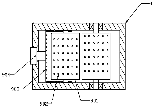
[0032]In this embodiment, dust is generated during the crushing process of the cloth. In order to prevent the dust from scattering and...


PUM


Abstract

The invention discloses a cloth waste treatment device for spinning. The cloth waste treatment device comprises an outer shell, wherein the four corners of the bottom of the outer shell are connectedwith stand columns; the left upper part of the outer shell communicates with a feeding channel; the left side of the top of the feeding channel communicates with a hopper; the left end and the right end of the feeding channel are rotatably connected with conveying rollers; a conveyor belt is arranged between the two groups of conveying rollers in a sleeving mode; the top of the inner cavity of thefeeding channel is connected with an electric heating wire; the upper part of the inner cavity of the outer shell is symmetrically connected with guide inclined plates left and right; a crushing mechanism is arranged below the guide inclined plates; the left side wall of the inner cavity of the outer shell is connected with a mounting base; the bottom of the mounting base is connected with a vibrating motor; the lower end of the vibrating motor is in power connection with a screen; the right side wall of the outer shell is equipped with a reflux mechanism; and the bottom of the inner cavity of the outer shell is connected with a discharge bin. The cloth waste treatment device is reasonable in structural design, can dry cloth waste, is beneficial for improving the crushing effect, and introduces unqualified fragments into the outer shell again to crush through the reflux mechanism, so that the cloth waste treatment effect is improved.

Description

technical field [0001] The invention relates to the technical field of textile machinery, in particular to a rag processing device for textile use. Background technique [0002] Textile machinery is all kinds of mechanical equipment needed to process natural fibers or chemical fibers into textiles. Although the machinery for producing chemical fibers includes a variety of chemical machinery, it is now considered an extension of textile machinery and belongs to textile machinery in a broad sense. The processes required to process different fibers such as cotton, hemp, silk, wool, etc. into textiles are not the same, and some are completely different, so the machines required are also various and varied. Textile machinery is usually classified according to the production process, including: spinning equipment, weaving equipment, printing and dyeing equipment, finishing equipment, chemical fiber spinning equipment, reeling equipment and non-woven fabric equipment. Spinning eq...

Claims


Application Information

Patent Timeline
IPC IPC(8): B02C4/08B02C4/28B02C23/02B02C4/32B02C23/12B02C23/16B02C23/18B08B15/00F26B23/06
CPCB02C4/08B02C4/28B02C4/286B02C4/32B02C23/12B02C23/16B02C23/18B02C2023/165B02C2201/06B08B15/007F26B23/06
Inventor 胡达
Owner 湖北延昌纺织股份有限公司
Why Eureka
Try Eureka