
Cutting machine control method and control device

A control method and cutting machine technology, applied in the direction of computer control, program control, general control system, etc., can solve the problems of low arc striking success rate, achieve the effects of reducing loss, reducing production cost, and improving arc striking success rate

Inactive Publication Date: 2020-08-18
上海气焊机厂有限公司
View PDF9 Cites 1 Cited by
  • Summary
  • Abstract
  • Description
  • Claims
  • Application Information

AI Technical Summary

Problems solved by technology

Non-high-frequency cutting torch arc ignition has high requirements on timing control and arc ignition current parameters, and the success rate of arc ignition is low

Method used


Image

  • Cutting machine control method and control device
  • Cutting machine control method and control device
  • Cutting machine control method and control device

Examples


Embodiment Construction

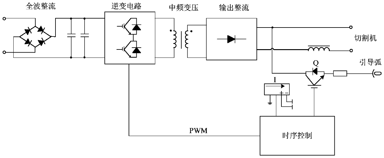
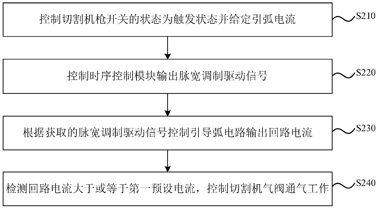
[0040] The present invention will be further described in detail below in conjunction with the accompanying drawings and embodiments. It should be understood that the specific embodiments described here are only used to explain the present invention, but not to limit the present invention. In addition, it should be noted that, for the convenience of description, only some structures related to the present invention are shown in the drawings but not all structures.

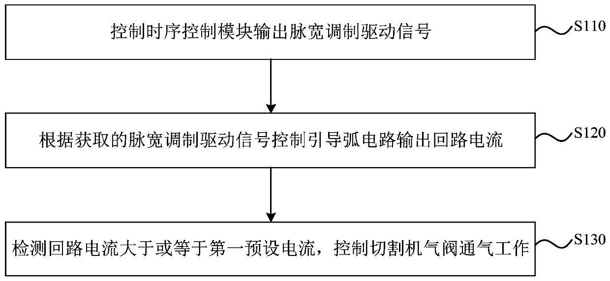
[0041] figure 1 A schematic flow chart of a cutting machine control method provided by an embodiment of the present invention, as shown in figure 1 As shown, the cutting machine control method includes:

[0042] S110. The control sequence control module outputs a pulse width modulation driving signal.

[0043] Pulse width modulated drive signaling is a method of digitally encoding the level of an analog signal. Through the use of high-resolution counters, the duty cycle of a square wave is modulated to encode th...


PUM


Abstract

The invention discloses a cutting machine control method and a control device. The control method comprises the following steps of controlling a time sequence control module to output a pulse width modulation driving signal; controlling an arc ignition circuit to output loop current according to the obtained pulse width modulation driving signal; and detecting whether the loop current is greater than or equal to first preset current, and controlling a cutting machine air valve to ventilate and work. According to the technical scheme provided by the embodiment of the invention, the control module outputs the pulse width modulation driving signal to control the arc ignition circuit to output the loop current, so that the arc ignition success rate of the cutting machine is increased, the lossof a nozzle and an electrode is reduced, and the production cost is reduced.

Description

technical field [0001] The invention relates to the control field of plasma non-high-frequency cutting machines, in particular to a cutting machine control method and control device. Background technique [0002] The name plasma arc cutting comes from the term "plasma (PLASMA)", plasma refers to ionized gaseous matter, known as the fourth state of matter. In modern physics, a gas with an ionization degree greater than 0.1% is called a plasma. [0003] Due to the higher degree of ionization, higher energy density, higher temperature, and higher flame flow velocity of the gas in the plasma arc after the arc is compressed, when the ionized gas is ionized, a high-temperature ion flow will be generated and ejected from a fine hole , After being compressed, it forms a slender arc column, and the temperature is as high as 18000K-24000K. It has the characteristics of slender arc column and high energy density. Therefore, it can be used to make plasma arc cutting. There are general...

Claims


Application Information

Patent Timeline
Patent Type & Authority Applications(China)
IPC IPC(8): B23K10/00G05B19/4065
CPCB23K10/006G05B19/4065G05B2219/37616
Inventor 不公告发明人
Owner 上海气焊机厂有限公司
Learn More