A method for controlling the gas flow of an air plasma cutting machine

An air plasma and gas flow technology, applied in plasma welding equipment, manufacturing tools, welding equipment, etc., can solve the problems of time-wasting materials, processing quality impact, finished product use and delivery troubles, etc., to achieve arc stability and improve arc ignition success. rate and ensure the effect of cutting depth

Active Publication Date: 2015-12-09
湖南超宇科技有限公司
View PDF9 Cites 0 Cited by
  • Summary
  • Abstract
  • Description
  • Claims
  • Application Information

AI Technical Summary

Problems solved by technology

However, the control of the gas flow rate of the existing plasma cutting machine is completely dependent on manual setting and experience. Sometimes repeated experiments are required, which wastes time and materials. If the flow rate is not set properly, it will also affect the processing quality and affect the use of finished products. and deliver troubles

Method used


Image

  • A method for controlling the gas flow of an air plasma cutting machine
  • A method for controlling the gas flow of an air plasma cutting machine
  • A method for controlling the gas flow of an air plasma cutting machine

Examples


Embodiment Construction

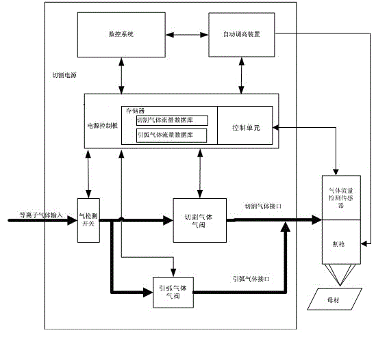
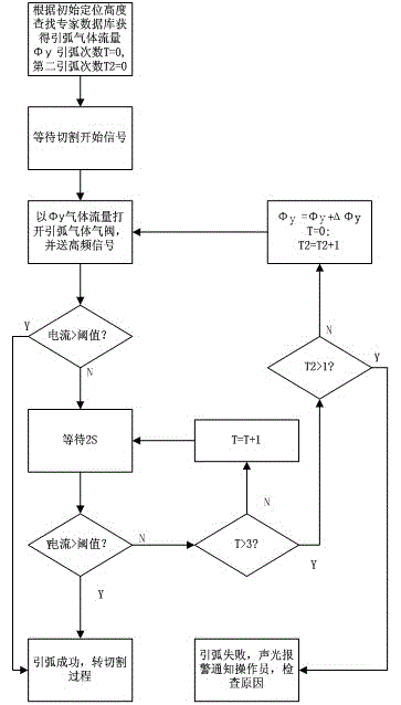
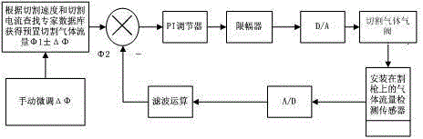
[0029] Such as Figure 1 to Figure 3 , use the cutting current and cutting speed to establish the gas flow database, and store it in the flash memory FLASH of the micro control unit MCU in the plasma cutting machine. Before the cutting starts, the operator sets the cutting thickness H, cutting Current I, cutting speed S and other parameters, and send these parameters to the micro control unit MCU in the plasma cutting machine, the MCU in the plasma cutting machine searches the database according to the cutting current and cutting speed During the cutting process, the gas flow sensor detects the gas flow in a timely manner, and after signal processing by the filter circuit, it is sent to the MCU in the plasma cutting machine for A / D sampling, and the actual gas is obtained after software filtering and calculation. Flow Φ2, compare Φ1 and Φ2 to get the deviation signal, the deviation signal is calculated by the limit weakening integral PI control algorithm, the calculated deviat...


PUM


Abstract

The invention relates to a gas flow control method of an air plasma cutting machine. The method comprises the following steps that a gas flow database is built; parameters of the board thickness H, the current I and the cutting speed S are input in a numerical control system before cutting is started, and a matched gas flow phi 1 of the gas flow database is searched; in the cutting process, an actual gas flow signal phi 2 is detected, and after a control unit compares the matched gas flow phi 1 with the actual gas flow signal phi 2, the actual gas flow phi 2 and the flow deviation delta phi are obtained; an executing mechanism controls a gas valve through the flow deviation delta phi, and the flow deviation delta phi tends to zero. The invention further relates to a gas flow control system of the air plasma cutting machine. The gas flow control system of the air plasma cutting machine comprises the numerical control system, the gas valve, a gas detection switch, a sensor and a cutting gun, and further comprises a power control board, wherein the power control board comprises a control unit and a storage; the control unit is connected with the storage; the numerical control system, the power control board, the gas detection switch and the gas valve are sequentially connected and then are connected with the sensor and the cutting gun; the control unit is connected with the sensor. The cutting gas flow is best matched with the cutting current and the cutting speed, and the gas flow control method and system have the advantages that plasma jet flow can be stably formed and an electric arc is stable.

Description

technical field [0001] The invention relates to a control method of an air plasma cutting machine, in particular to a gas flow control method for improving the arc striking success rate and cutting quality of a high-power air plasma cutting machine. Background technique [0002] The air plasma cutting machine is mainly used in metal and non-metal cutting, and belongs to the technical field of air plasma cutting equipment. Air plasma arc cutting is a cutting method using high-temperature and high-speed heat flow generated by a high-energy-density compressed arc. The movement of the plasma arc torch forms the kerf. Using compressed air as the ion gas for plasma arc cutting has the advantages of convenient gas source, low cutting cost, high cutting speed, and good incision quality. It has developed into the most widely used plasma cutting method. In particular, the high-power air plasma cutting machine and CNC are matched to form a CNC cutting system, which is widely used in ...

Claims


Application Information

Patent Timeline
Patent Type & Authority Patents(China)
IPC IPC(8): B23K10/00
CPCB23K10/00B23K10/006
Inventor 陈军根谢越群
Owner 湖南超宇科技有限公司
Why Eureka
Try Eureka