Method for operating a fuel system, control unit and fuel system

A fuel system and control unit technology, applied in fuel injection control, charging system, electrical control, etc., can solve the problem of slow gas pressure adjustment, achieve the effects of optimizing vibration performance, simplifying structure, and simplifying the fuel system

Pending Publication Date: 2020-08-18
ROBERT BOSCH GMBH
View PDF0 Cites 2 Cited by
  • Summary
  • Abstract
  • Description
  • Claims
  • Application Information

AI Technical Summary

Problems solved by technology

However, due to the high compressibility of the gaseous fuel, the regulation of the gas pressure via such a pressure regulator takes place very slowly
Additionally, a large amount of control traffic is lost from the system

Method used


Image

  • Method for operating a fuel system, control unit and fuel system
  • Method for operating a fuel system, control unit and fuel system

Examples


Embodiment Construction

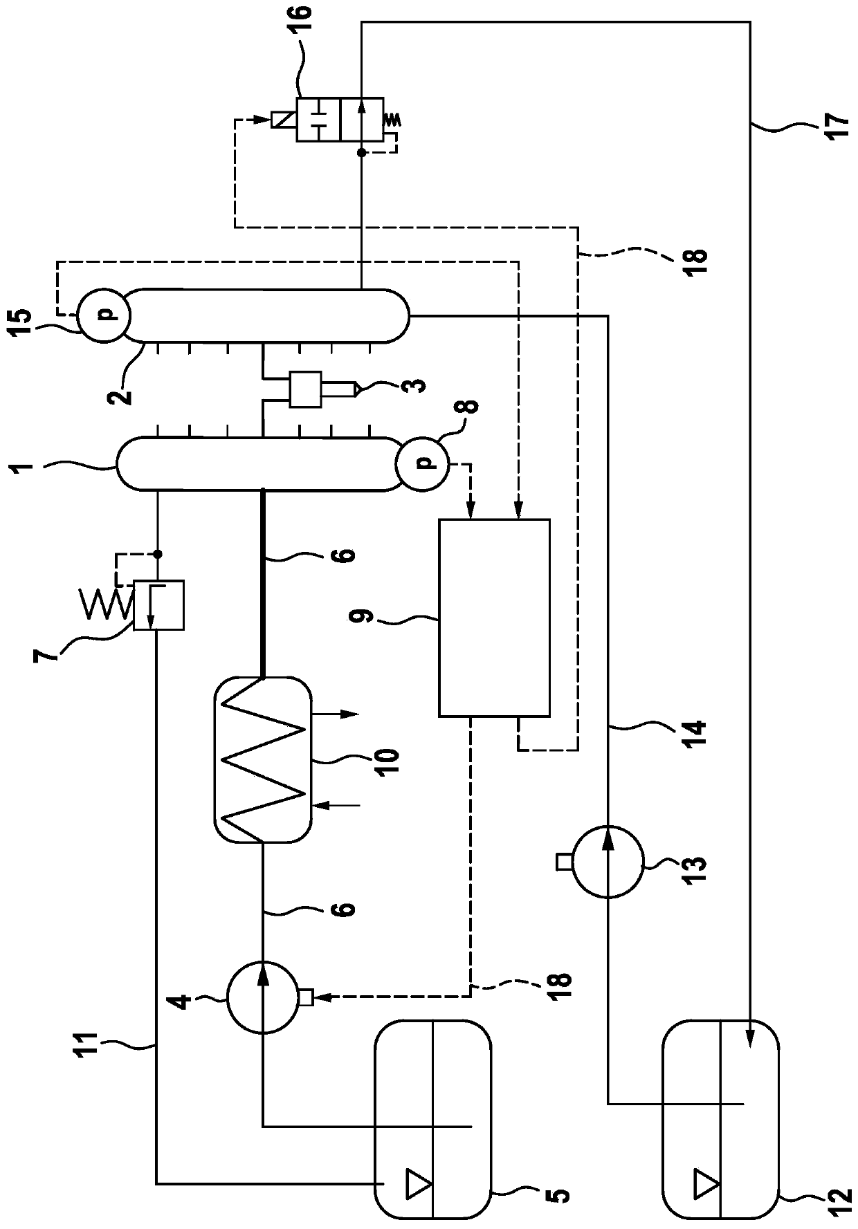
[0026] exist figure 1 The fuel system shown in is used to supply an internal combustion engine with a first gaseous fuel (such as natural gas) and a second liquid fuel (such as diesel fuel). The fuel is blown or injected into the combustion chamber of the internal combustion engine by means of at least one dual-mass injector 3 . At least one dual-mass injector 3 is supplied with both fuels via a gaseous rail 1 and a liquid fuel rail 2 , wherein the liquid fuel simultaneously serves as the control medium.

[0027] The fuel system shown comprises on the gas side a tank 5 which is connected to the gas rail via a gas supply line 6 and a fuel pump 4 by which gaseous fuel from the tank 5 can be supplied to the gas rail 1 . Furthermore, a heat exchanger 10 is arranged in the gas supply line 6 between the fuel pump 4 and the gas rail 1 . The section of the gas supply line 6 which connects the heat exchanger 10 to the gas rail 1 now has an increased flow diameter which leads to an in...


PUM


Abstract

The invention relates to a method for operating a fuel system of an internal combustion engine. The fuel system comprises a gas rail (1) for a first gaseous fuel and a liquid fuel rail (2) for a liquid second fuel as well as at least one two-fuel injector (3) connected to the gas rail (1) and to the liquid fuel rail (2) for blowing or injecting the fuels into a combustion chamber of the internal combustion engine, wherein the liquid fuel is also used as a control medium. According to the method, the pressure in the liquid fuel rail (2) is changed to shape the injection rate of the gaseous fuelas a function of the operating point, while the pressure in the gas rail (1) is kept essentially constant at a pressure level. The invention also relates to a control unit (9) and a fuel system withsuch a control unit (9).

Description

technical field [0001] The invention relates to a method for operating a fuel system of an internal combustion engine. Furthermore, the invention relates to a control unit and a fuel system with such a control unit. The fuel system is particularly suitable for carrying out the method according to the invention or can be operated according to the method according to the invention. Background technique [0002] When burning gaseous fuels, such as natural gas (NG, “Natural Gas”), higher and higher injection pressures are achieved in order to meet the requirements at full load as are imposed for the combustion of diesel fuel. However, a high injection pressure leads to an injection rate that is too high in partial load operation of the internal combustion engine and is often implemented with undesired noise generation and / or increased emissions. This situation should be avoided. [0003] As a solution, a pressure regulating valve for gas pressure regulation can be provided on...

Claims


Application Information

Patent Timeline
IPC IPC(8): F02D19/08F02M21/02F02D41/30F02D41/38F02M43/04
CPCF02D19/08F02M21/0215F02M21/0221F02M21/023F02D41/30F02D41/3836F02M43/04F02D2041/3881F02D19/0694F02D19/0647F02M43/00F02M21/0218F02M21/0245Y02T10/30
Inventor A·克尔纳J·韦斯内尔M·卡茨T·施内肯布格尔
Owner ROBERT BOSCH GMBH
Why Eureka
Try Eureka