Steam turbine pump control cylinder servo system and control method

A technology of servo system and steam turbine, which is applied in the field of steam turbine pump control cylinder servo system and its control, which can solve the problems of poor anti-pollution ability of the system, high oil supply pressure, and difficult degradation of fuel oil, so as to overcome poor anti-pollution ability and poor operation The effect of simple control and good application prospects

Active Publication Date: 2020-08-18
杭州澎康自动化科技有限公司
View PDF8 Cites 3 Cited by
  • Summary
  • Abstract
  • Description
  • Claims
  • Application Information

AI Technical Summary

Problems solved by technology

[0003] (1) Low-pressure turbine oil-electro-hydraulic servo system, the system oil source is shared with lubricating oil, including oil filter device, safety oil pressure establishment device, OPC solenoid valve, electro-hydraulic servo valve, wrong throttle slide valve, oil cylinder and displacement sensor, etc. Composition, low-pressure turbine oil electro-hydraulic servo system has low pressure oil, generally less than 2MPa, large oil cylinder design, slow response, and poor anti-pollution ability of the system due to sharing oil source with lubricating oil
[0004] (2) Independent high-voltage electro-hydraulic servo system, the system is designed with a set of independent hydraulic oil station, the oil supply pressure is relatively high, generally 10~MPa, according to different working fl

Method used


Image

  • Steam turbine pump control cylinder servo system and control method
  • Steam turbine pump control cylinder servo system and control method

Examples


Embodiment Construction

[0028] The embodiments of the invention will be further described below in conjunction with the embodiments.

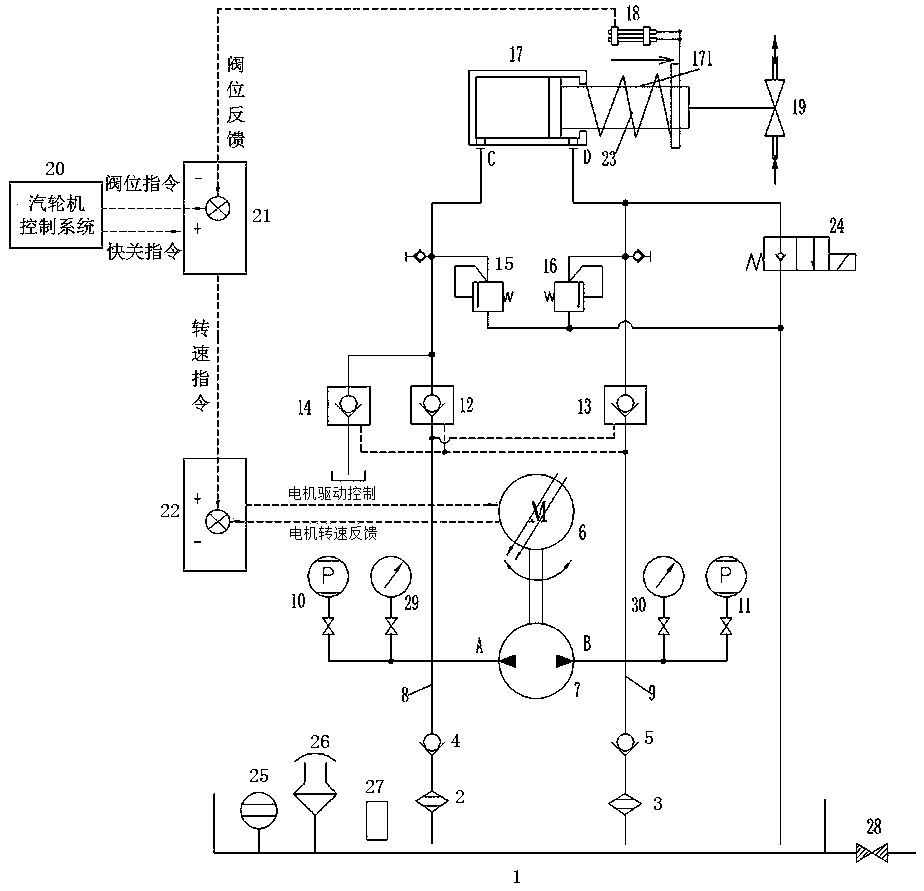
[0029] Such as figure 1 As shown, a pump control cylinder servo system for a steam turbine includes an oil charge tank 1, a first oil suction filter 2, a second oil suction filter 3, a first check valve 4, a second check valve 5, and a servo motor 6 , two-way hydraulic pump 7, first oil inlet pipeline 8, second oil inlet pipeline 9, first pressure sensor 10, second pressure sensor 11, first hydraulic control check valve 12, second hydraulic control check valve 13, The third hydraulic control check valve 14, the first relief valve 15, the second relief valve 16, the oil cylinder 17, the displacement sensor 18, the steam turbine regulating valve 19, the steam turbine control system 20, the position controller 21, the servo driver 22, reset Spring 23, unloading solenoid valve 24, temperature transmitter 25, air filter 26, liquid level gauge 27, oil drain valve 28, first...


PUM


Abstract

The invention relates to a steam turbine pump control cylinder servo system and control method. The steam turbine pump control cylinder servo system comprises an oil cylinder, a servo driver, a servomotor and a hydraulic oil pump, and further comprises an oil supplementing tank, a displacement sensor and a position controller; the displacement sensor, the position controller, the servo driver andthe servo motor are electrically connected; the position controller is electrically connected to a steam turbine control system, and the oil supplementing tank is connected to an input port of the hydraulic oil pump through an oil suction filter, a one-way valve and an oil inlet pipeline in sequence; and the hydraulic oil pump is connected to the oil cylinder through a hydraulic control one-way valve and an overflow valve in sequence, a reset spring used for pushing a piston arranged in the oil cylinder is further arranged in the oil cylinder, the piston is connected to a steam turbine adjusting valve, and the oil cylinder is connected to the oil supplementing tank through an unloading electromagnetic valve. According to the steam turbine pump control cylinder servo system, pressure oil is output in two directions through the two-way hydraulic oil pump to control the oil cylinder, meanwhile, opening and closing of the steam turbine adjusting valve are controlled, and the oil cylindercan be directly closed by controlling the unloading electromagnetic valve through a quick-closing instruction.

Description

technical field [0001] The invention relates to the technical field of steam turbine control, in particular to a steam turbine pump control cylinder servo system and a control method thereof. Background technique [0002] Industrial steam turbines are large-scale high-speed prime movers. They usually work under high temperature and high pressure. Their regulating valves require large driving force, fast response and high-precision control. Generally, electro-hydraulic servo control systems are used. Traditional steam turbine electro-hydraulic servo systems use The valve-controlled cylinder servo control form, that is, the pressure oil is supplied by the oil source system, and the oil cylinder is controlled through the electro-hydraulic servo valve (also called "oil motor"). Oil source pressure can be divided into low-pressure turbine oil-electro-hydraulic servo system and independent high-voltage electro-hydraulic servo system. [0003] (1) Low-pressure turbine oil-electro-...

Claims


Application Information

Patent Timeline
IPC IPC(8): F15B11/08F15B13/02F15B21/041F15B19/00F15B21/08
CPCF15B11/08F15B13/027F15B13/02F15B21/041F15B19/00F15B21/08
Inventor 纪云锋屠昌锋郑志明谭爱林
Owner 杭州澎康自动化科技有限公司
Why Eureka
Try Eureka