Variable-mass power centrifuge and experimental method

A centrifuge and variable quality technology, applied in the direction of centrifuges, measuring devices, vibration testing, etc., can solve the problems of low-frequency driving difficulties, complex structures, high driving voltage, etc., and achieve simple and reliable connection methods, simple implementation methods, and compact device structures Effect

Active Publication Date: 2020-08-25
XI AN JIAOTONG UNIV
View PDF7 Cites 0 Cited by
  • Summary
  • Abstract
  • Description
  • Claims
  • Application Information

AI Technical Summary

Problems solved by technology

Piezoelectric-driven vibrating tables require high driving voltage, large loss, and difficult low-frequency driving; mechanical vibrating tables are driven by spring mechanisms, and the driving force is small, and the waveform provided is single, and the frequency adjustable range is low due to the spring stiffness coefficient; Vibration table, the medicine chamber is placed in the model box, and the vibration environment is simulated by compressed air. The repeatability is poor and the amplitude is difficult to control; the electromagnetic vibration table has a large volume and weight, a large current, and a small driving force; the electro-hydraulic servo vibration table is currently the most commonly used The vibration experiment system can provide multi-directional and multi-frequency excitation force, which can well meet the experimental requirements of the dynamic centrifuge, but it needs to design the electro-hydraulic servo actuator and the layout method in the limited space of the hanging basket, which is expensive and difficult to construct. complex

Method used


Image

  • Variable-mass power centrifuge and experimental method
  • Variable-mass power centrifuge and experimental method
  • Variable-mass power centrifuge and experimental method

Examples


Embodiment Construction

[0067] Realization of shock loads in a centrifugal vibration environment:

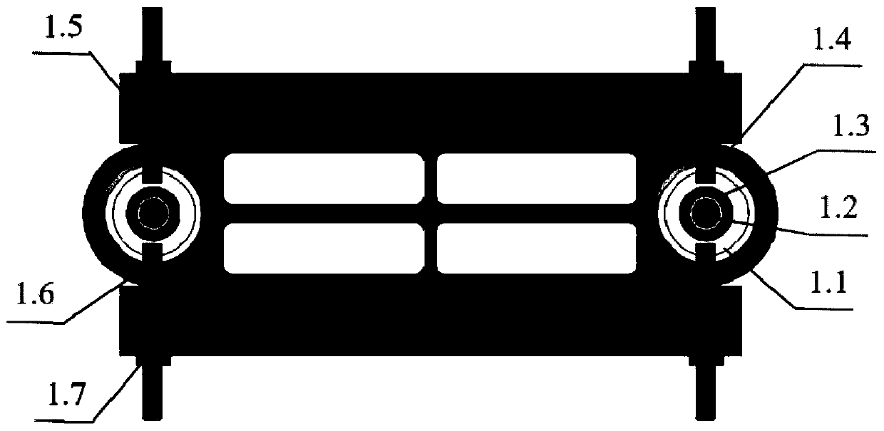
[0068] The additional quality block 1.5 is enough, when the relatively large DC voltage is transmitted to the power supply device 3.3 through the circuit transmission system 5.1, and is transmitted to the electromagnetic coil 3.2 by the power supply device 3.3 through four branch circuits 3.4, at this time, a relatively high voltage is induced on the electromagnet core 3.1. Large electromagnetic force, the force interacts with the permanent magnet 1.2, and the moment of inertia of the system changes transiently. According to the conservation of momentum moment, the corresponding rotational angular acceleration and angular velocity also change accordingly; the two sliding masses move toward ( or away from) the electromagnetic device moves in 3 directions, at this time, a transient acceleration will be generated to act on the test piece to realize transient impact load loading.

[0069] Realization of al...


PUM


Abstract

The invention discloses a variable-mass power centrifuge and an experimental method. Mass distribution of a centrifuge system is changed through electromagnetic force, so that the rotational inertia of the system is changed, the rotation angular velocity and the angular acceleration of the centrifuge are changed, and an excitation effect is achieved in both the radial and tangential directions. The power centrifuge comprises a fixed electromagnetic device, the generated electromagnetic force acts on a sliding mass block, so that the sliding mass block moves radially according to a certain rule, and the magnitude and the frequency of the electromagnetic force are adjustable; on the other hand, the sliding mass block is adjustable in size, and the size of the sliding mass block can be increased or decreased according to specific experimental requirements. A plurality of experiment cabins can be arranged on an experiment table, power centrifugal experiments with the same excitation frequency but different excitation amplitudes can be carried out for experimental parts in the same type at the same time, and comparative experiments under the same excitation environment can be carried out for different experimental parts. The adverse effect of hydraulic excitation is avoided, a novel method is provided for multidirectional excitation, multiple different types of excitation can be realized, operation is simple and convenient, and control is convenient.

Description

technical field [0001] The invention relates to the field of power centrifuges, in particular to a variable mass power centrifuge and a power centrifuge experiment method. Background technique [0002] In addition to providing centrifugal force during operation, the power centrifuge also needs to provide exciting force. The provision of exciting force requires a power source and exciting equipment. Due to the strong coupling nonlinearity of the power centrifuge and the complexity of its own experimental conditions, the technical difficulty and operation requirements of the shaking table are very high. [0003] At present, the power centrifuge mainly provides the exciting force through the vibrating table, and the types of the vibrating table include piezoelectric, electromagnetic, mechanical, explosive and electro-hydraulic. Piezoelectric-driven vibrating tables require high driving voltage, high loss, and low-frequency driving are difficult; mechanical vibrating tables are...

Claims


Application Information

Patent Timeline
IPC IPC(8): B04B9/00B04B9/08G01M7/02
CPCB04B9/00B04B9/08G01M7/022
Inventor 张亚红鲁文超郑宜生罗亚军谢石林路广霖
Owner XI AN JIAOTONG UNIV
Why Eureka
Try Eureka