Radiation refrigeration fiber design method and radiation refrigeration fiber
A technology of radiation cooling and design method, applied in the design of radiation cooling fibers and in the field of radiation cooling fibers, which can solve the problems of complex preparation methods, high cost, and poor effect, and achieve high solar spectrum reflection efficiency, stable structure, and good visibility- Effect of near-infrared light reflectance properties
- Summary
- Abstract
- Description
- Claims
- Application Information
AI Technical Summary
Problems solved by technology
Method used
Image
Examples
Embodiment 1
[0073] The polymer base material is PMMA, and the micro-nano particle material is TiO 2 According to the above method, the optimal particle size of the micro-nano particles is selected as 600nm, and the volume fraction of the micro-nano particles in the fiber is determined to be 10%, so as to obtain the radiative cooling fiber, and the thickness of the fabric made of the fiber is 50 μm.
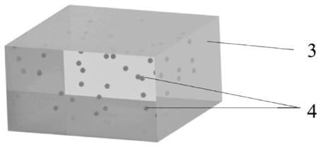
[0074] FDTD Soultions was used to construct a three-dimensional PMMA cube whose thickness was determined to be 50 μm, in which TiO with a volume fraction of 10% and a diameter of 600 nm was randomly distributed 2 particles. Using the simulation settings described in step S5, the visible-near-infrared light reflectance curve and the 7 μm-14 μm band emissivity of the fabric composed of the fibers are calculated, such as Figure 6 indicated by the dotted line.
[0075] According to the above reflectance and emissivity curves, the weighted reflectance of the corresponding solar spectrum is calc...
Embodiment 2
[0077] The polymer base material is PMMA, and the micro-nano particle material is TiO 2 According to the above method, the optimal particle size of the micro-nano particles is selected as 600nm, and the volume fraction of the micro-nano particles in the fiber is determined to be 10%, so as to obtain the radiative cooling fiber, and the thickness of the fabric made of the fiber is 100 μm.
[0078] FDTD Soultions was used to construct a three-dimensional PMMA cube whose thickness was determined to be 100 μm, in which TiO with a volume fraction of 10% and a diameter of 600 nm was randomly distributed 2 particles. Using the simulation settings described in step S5, the visible-near-infrared light reflectance curve and the 7 μm-14 μm band emissivity of the fabric composed of the fibers are calculated, such as Figure 6 shown in the dotted line, and Figure 7 shown by the solid line.
[0079] According to the above reflectance and emissivity curves, the weighted reflectance of th...
Embodiment 3
[0081] The polymer base material is PMMA, and the micro-nano particle material is TiO 2 According to the above method, the optimal particle size of the micro-nano particles is selected as 600nm, and the volume fraction of the micro-nano particles in the fiber is determined to be 10%, so as to obtain the radiative cooling fiber, and the thickness of the fabric made of the fiber is 200 μm.
[0082] A three-dimensional PMMA cube with a thickness of 200 μm was constructed using FDTD Soultions, in which TiO with a volume fraction of 10% and a diameter of 600 nm was randomly distributed 2 particles. Using the simulation settings described in step S5, the visible-near-infrared light reflectance curve and the 7 μm-14 μm band emissivity of the fabric composed of the fibers are calculated, such as Figure 6 shown by the solid line.
[0083] According to the above reflectance and emissivity curves, the weighted reflectance of the corresponding solar spectrum is calculated to be 0.96, a...
PUM
| Property | Measurement | Unit |
|---|---|---|
| Diameter | aaaaa | aaaaa |
| Thickness | aaaaa | aaaaa |
Abstract
Description
Claims
Application Information
 - R&D
- Intellectual Property
- Life Sciences
- Materials
- Tech Scout
- Unparalleled Data Quality
- Higher Quality Content
- 60% Fewer Hallucinations
Browse by: Latest US Patents, China's latest patents, Technical Efficacy Thesaurus, Application Domain, Technology Topic, Popular Technical Reports.
© 2025 PatSnap. All rights reserved.Legal|Privacy policy|Modern Slavery Act Transparency Statement|Sitemap|About US| Contact US: help@patsnap.com


