Magnetic field detector based on surface enhanced Raman scattering
A surface-enhanced Raman and detector technology, applied in the field of magnetic field detection, can solve the problems of high detection limit and low sensitivity, and achieve the effect of low detection limit and high sensitivity
- Summary
- Abstract
- Description
- Claims
- Application Information
AI Technical Summary
Problems solved by technology
Method used
Image
Examples
Embodiment 1
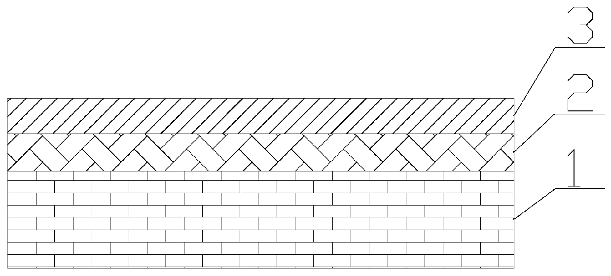
[0019] The invention provides a magnetic field detector based on surface-enhanced Raman scattering. The magnetic field detector includes a light source, a photodetector, a substrate 1 , a deformation layer 2 and a noble metal layer 3 . Such as figure 1 As shown, the deformation layer 2 is placed on the substrate 1 , and the noble metal layer 3 is placed on the deformation layer 2 . The deformation layer 2 includes a first magnetostrictive material, and the noble metal layer 3 includes noble metal particles, and the material of the noble metal particles is gold.
[0020] When measuring the magnetic field, chemical molecules, such as rhodamine 6G molecules, are arranged on the noble metal layer 3 . The noble metal layer 3 is irradiated with a light source. The light source is a monochromatic light source, such as a light source with a wavelength of 532 nanometers. The light source excites the chemical molecules to produce surface-enhanced Raman scattering, and the light detec...
Embodiment 2
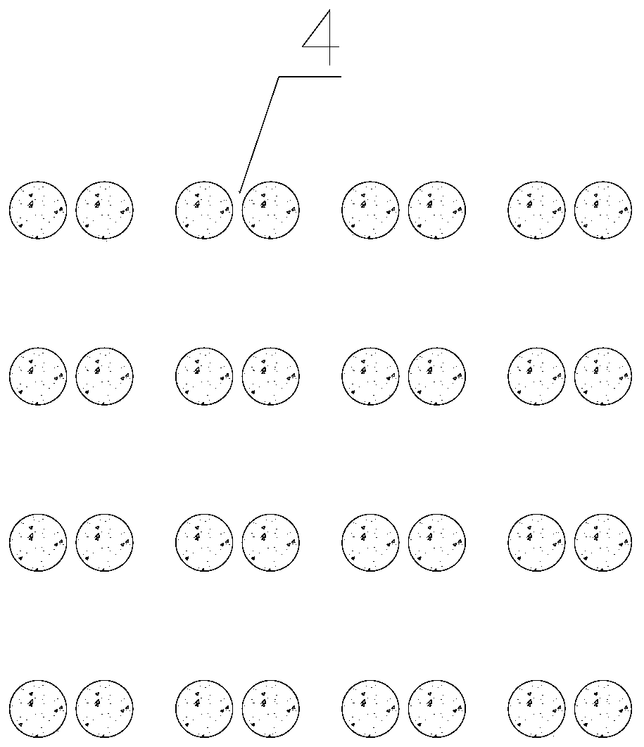
[0025] On the basis of Example 1, the magnetostriction coefficient of the first magnetostrictive material is a positive value. The noble metal nanoparticles contain an inner core, and the inner core is a second magnetostrictive material. The magnetostriction coefficient of the second magnetostrictive material is negative. The magnetostriction coefficient of the first magnetostrictive material is positive, such as iron; the magnetostriction coefficient of the second resignation stretchable material is negative, such as nickel. Under the action of the magnetic field to be measured, the first magnetostrictive material expands to increase the distance between the noble metal particles; the second magnetostrictive material contracts to increase the distance between the noble metal particles due to the reduction in the size of the noble metal particles. The effects of these two aspects will increase the distance between the noble metal particles and change the electric field betwee...
Embodiment 3
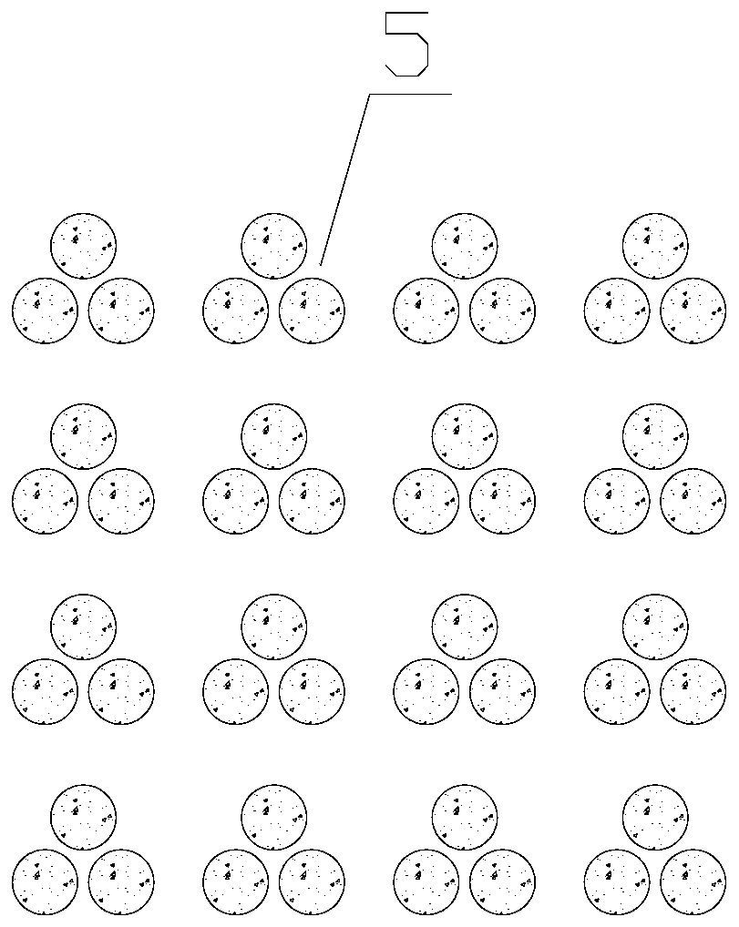
[0027] On the basis of Example 2, the heights of the noble metal nanostructure trimer 5 are different. That is, the height of the trimer as a unit is not the same. For adjacent nanostructures with different heights, under the action of excitation light, in addition to the electric field coupling between the nanostructures in the horizontal direction, the electric field coupling along the height direction will also occur. When the distance between nanostructures is changed, the electric field coupling in the horizontal direction and the electric field coupling in the height direction are changed at the same time, the electric field near the nanostructures is changed more, the signal intensity of surface-enhanced Raman scattering is changed more, and the magnetic field is increased. Sensitivity of detection.
PUM
 Abstract
Description
Claims
Application Information
 - R&D
- Intellectual Property
- Life Sciences
- Materials
- Tech Scout
- Unparalleled Data Quality
- Higher Quality Content
- 60% Fewer Hallucinations
Browse by: Latest US Patents, China's latest patents, Technical Efficacy Thesaurus, Application Domain, Technology Topic, Popular Technical Reports.
© 2025 PatSnap. All rights reserved.Legal|Privacy policy|Modern Slavery Act Transparency Statement|Sitemap|About US| Contact US: help@patsnap.com


