
Sewage and wastewater source steam compression dry heat pump unit

A technology of heat pump units and compression drying, which is applied in heat pumps, refrigerators, refrigeration components, etc., can solve the problems of inability to use waste heat and heat sources of industrial sewage and waste water, and achieve the effects of recycling, efficient and clean utilization, and improving heat exchange efficiency

Pending Publication Date: 2020-08-28
HIT HARBIN INST OF TECH KINT TECH
View PDF0 Cites 2 Cited by
  • Summary
  • Abstract
  • Description
  • Claims
  • Application Information

AI Technical Summary

Problems solved by technology

[0005] The present invention aims to solve the problem that the existing compression heat pumps cannot use industrial sewage and waste water as the waste heat source, and further provides a sewage and waste water source steam compression dry heat pump unit

Method used


Image

  • Sewage and wastewater source steam compression dry heat pump unit
  • Sewage and wastewater source steam compression dry heat pump unit
  • Sewage and wastewater source steam compression dry heat pump unit

Examples


specific Embodiment approach 1

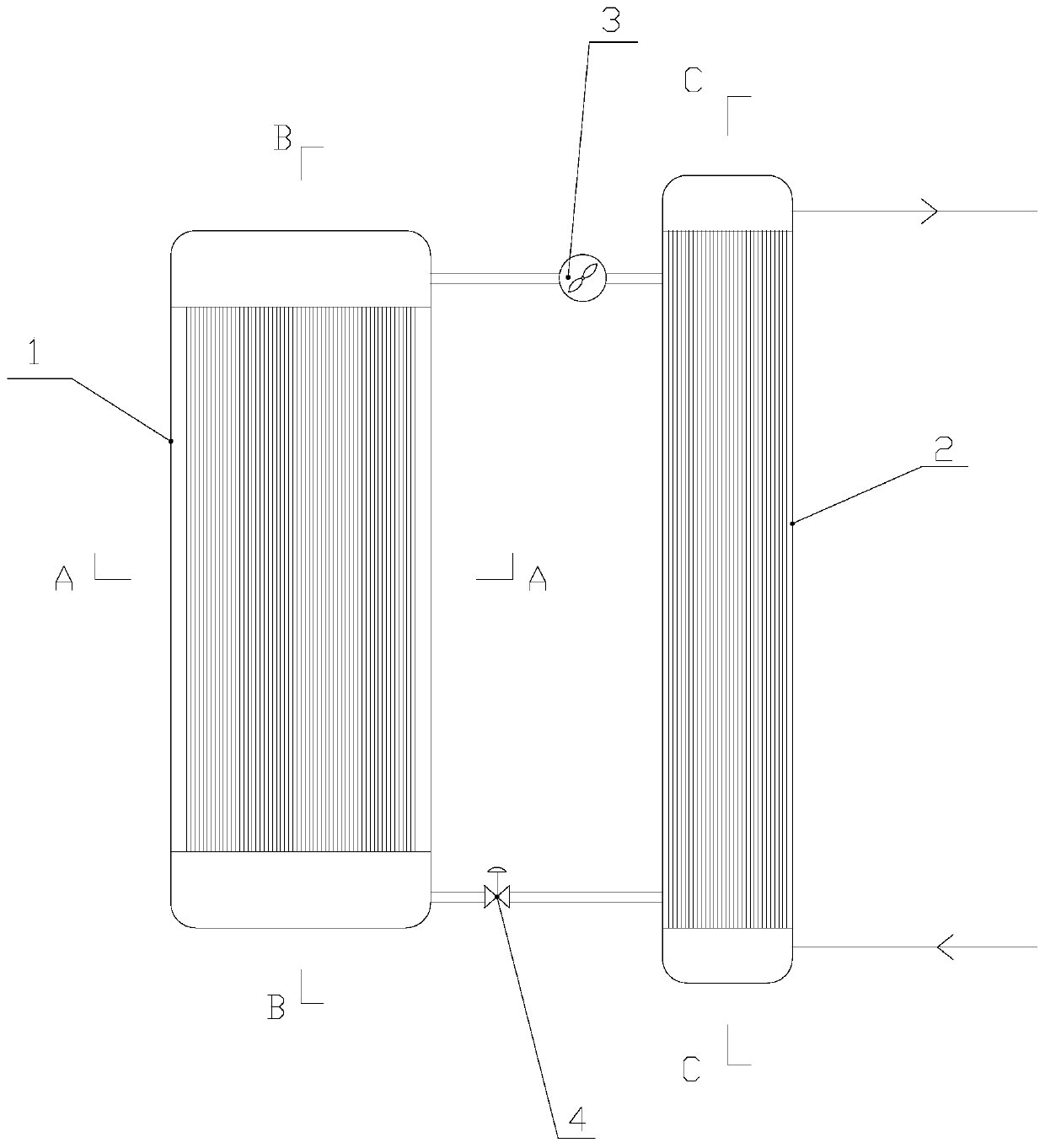
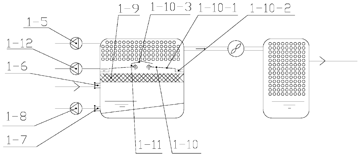
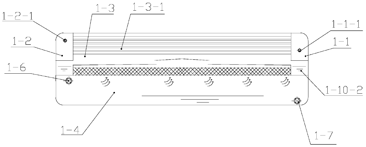
[0028] Specific implementation mode one: combine Figure 1~6 Description of this embodiment, the waste water source vapor compression dry heat pump unit includes an evaporator 1, a condenser 2, a compressor 3 and an expansion valve 4,

[0029] The evaporator 1 includes a working fluid inlet chamber 1-1 and a working fluid outlet chamber 1-2, and the condenser 2 is respectively communicated with the working fluid inlet chamber 1-1 and the working fluid outlet chamber 1-2 through pipelines. The expansion valve 4 is arranged on the pipeline between the working fluid inlet chamber 1-1 and the condenser 2, and the compressor 3 is arranged on the pipeline between the working fluid outlet chamber 1-2 and the condenser 2,

[0030] The evaporator 1 also includes a first heat exchange chamber 1-3 located on the upper part and a flash chamber 1-4 connected and arranged below the first heat exchange chamber 1-3, and the working fluid enters the chamber 1-1 and the working fluid The mass ...


PUM


Abstract

The invention discloses a sewage and wastewater source steam compression dry heat pump unit, and belongs to the technical field of waste heat utilization. The problem that an existing compression typeheat pump cannot utilize industrial sewage and wastewater to serve as a waste heat source is solved by the sewage and wastewater source steam compression dry heat pump unit. An evaporator further comprises a first heat exchange chamber located on the upper portion and a flash evaporation chamber arranged below the first heat exchange chamber in a communicating mode. A working medium inlet chamberand a working medium outflow chamber are formed in the two ends of the first heat exchange chamber in a communicating mode respectively. A vacuum pump is arranged on the upper portion of the evaporator in a communicating mode, and the interiors of the first heat exchange chamber and the flash evaporation chamber are vacuumized through the vacuum pump. A plurality of first heat exchange tubes arearranged in the first heat exchange chamber, and the working medium inlet chamber communicates with the working medium outflow chamber through the first heat exchange tubes. Sewage and wastewater enter the flash evaporation chamber to be subjected to flash evaporation through a sewage and wastewater inlet pipe in a communicating mode, steam which is obtained after flash evaporation is accomplishedmoves upwards to enter the first heat exchange chamber and exchanges heat with working media in the first heat exchange tubes, and the sewage and the wastewater obtained after flash evaporation are discharged from the evaporator through a sewage and wastewater receding pipe.

Description

technical field [0001] The invention relates to a waste water source steam compression dry heat pump unit, which belongs to the technical field of waste heat utilization. Background technique [0002] The compression heat pump is a mechanical device that forces heat to flow from low-temperature objects to high-temperature objects in a reverse cycle manner. It only consumes a small amount of reverse cycle net work to obtain a large amount of heat supply, and can effectively transfer low-grade heat energy that is difficult to apply Use it to achieve energy saving purposes. [0003] There is a large amount of low-grade waste heat in municipal sewage, industrial wastewater or circulating water that can be used as a heat source for heat pumps. However, since this part of sewage and wastewater contains a large amount of suspended solids or dissolved solids, if these sewage and wastewater directly enter the heat pump unit, it is very easy to replace them. Problems such as blockage...

Claims


Application Information

Patent Timeline
Patent Type & Authority Applications(China)
IPC IPC(8): F25B30/02F25B30/06
CPCF25B30/02F25B30/06
Inventor 李伟黄伟成宋乃秋李金峰张勇尚德敏
Owner HIT HARBIN INST OF TECH KINT TECH
Learn More