Flue gas treatment system

A technology of flue gas treatment system and treatment section, which is applied in the field of waste heat boiler and industrial kiln flue gas treatment. It can solve the problems of high operating cost, high hardness of dust particles, and restrictions on the development of enterprises, so as to save desulfurization agent and occupy an area. Less, the effect of improving efficiency

Pending Publication Date: 2019-08-30
COAL IND JINAN DESIGN & RES
View PDF0 Cites 2 Cited by
  • Summary
  • Abstract
  • Description
  • Claims
  • Application Information

AI Technical Summary

Problems solved by technology

[0003] Waste heat boilers and industrial kilns have large flue gas flow rate changes, complex components, high dust concentration, large changes, high hardness and viscosity of dust particles, high flue gas temperature, and large temperature changes. Existing tail gas treatment mostly uses multi-pipe dust removal , Electrostatic dust removal, bag dust removal, and wet desulfurization process, resulting in complex system, large area, high resistance, high power consumption, high flue gas temperature, large changes, ultra-fine dust, difficult operation of dust removal equipment, resulting in pollution It is difficult to control the discharge of pollutants, the secondary pollution is serious, the operating cost is high, and the task of environmental protection is heavy, which seriously restricts the development of enterprises

Method used


Image

  • Flue gas treatment system

Examples


Embodiment Construction

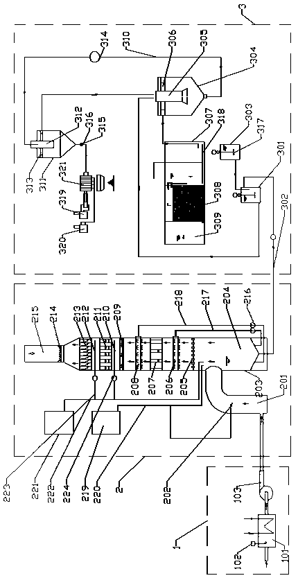
[0035] Accompanying drawing is the specific embodiment of the present invention. Such as figure 1 As shown, this kind of flue gas treatment system includes waste heat recovery section 1, washing and absorption section 2 and washing and absorption liquid treatment section 3, wherein:

[0036] The waste heat recovery section 1 includes a heat exchanger 101, which is used to lower the temperature of the exhaust gas from greater than 200°C to less than 150°C, and the recovered heat is used to produce hot water or steam for heating or other comprehensive utilization of flue gas after treatment. Install a soot blower 102 on the heat exchanger 101. The soot blower 102 is used to clean the heat exchange surface of the heat exchanger 101 to prevent fouling. The outlet end of the heat exchanger 101 is connected to a centrifugal fan 103 to improve exhaust The pressure is greater than 2000Pa to overcome the resistance of downstream equipment and facilities.

[0037] The washing and abso...


PUM


Abstract

The invention relates to the technical field of flue gas treatment of heat recovery boilers and industry kiln stoves, and specially discloses a flue gas treatment system. The flue gas treatment systemcomprises a waste heat recovery section, a washing absorption section and a washing absorption liquid treatment section, wherein the waste heat recovery section is used for cooling flue gas; the washing absorption section is used for washing and absorbing waste gas; the washing absorption liquid treatment section is used for performing environment-friendly treatment on waste liquid subjected to washing. The system disclosed by the invention integrates waste heat reuse, washing absorption and waste liquid treatment; after the treatment, waste gas and waste heat recycle is realized, energy consumption is reduced, emission concentration of sulfur dioxide is less than 20 mg/Nm<3>, emission concentration of dust is less than 5 mg/Nm<3>, waste water COD is lower than 50 mg/L, SS (suspended solid) is lower than 30 mg/L, PH maintains at around 7, and effects of governing air pollutants and water pollutants are realized.

Description

technical field [0001] The invention relates to the technical field of flue gas treatment of waste heat boilers and industrial kilns, in particular to a flue gas treatment system. Background technique [0002] Dust and sulfide in flue gas are the main air pollutants and the main factors causing smog and acid rain. [0003] Waste heat boilers and industrial kilns have large flue gas flow rate changes, complex components, high dust concentration, large changes, high hardness and viscosity of dust particles, high flue gas temperature, and large temperature changes. Existing tail gas treatment mostly uses multi-pipe dust removal , Electrostatic dust removal, bag dust removal, and wet desulfurization process, resulting in complex system, large footprint, high resistance, high power consumption, high flue gas temperature, large changes, ultra-fine dust, difficult operation of dust removal equipment, resulting in pollution It is difficult to control the emission of pollutants, the...

Claims


Application Information

Patent Timeline
Patent Type & Authority Applications(China)
IPC IPC(8): B01D53/78B01D53/50B01D50/00C02F9/04C02F11/121C02F11/122C02F103/18
CPCB01D50/00B01D53/50B01D53/78B01D2258/0283C02F1/001C02F1/5281C02F1/74C02F9/00C02F11/121C02F11/122C02F2001/007C02F2103/18
Inventor 杨影影陆阳刘继猛王恩磊杨守彬杨怀玉黄军伟陈公卫郝振利
Owner COAL IND JINAN DESIGN & RES
Why Eureka
Try Eureka