
Pneumatic flow dividing, spraying and desulfurizing equipment
The technology of desulfurization equipment and spray device is applied in the field of pneumatic split-spray spray desulfurization equipment. , Extend the time of strong mass transfer, good dehydration effect
- Summary
- Abstract
- Description
- Claims
- Application Information
AI Technical Summary
Problems solved by technology
Method used
Image

Examples
Embodiment Construction
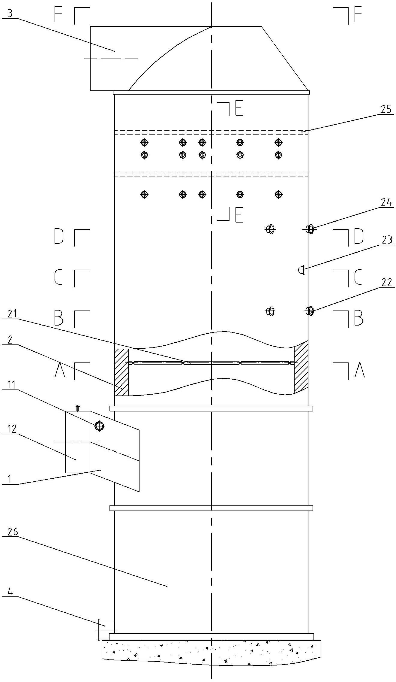
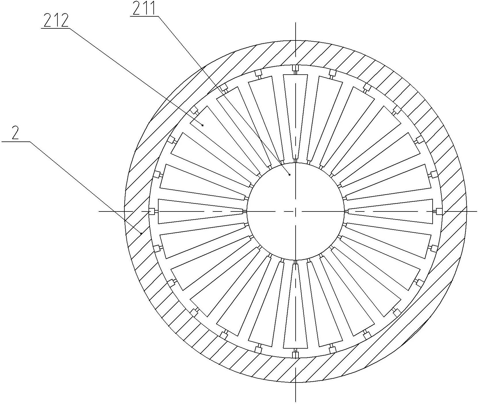
[0028] like figure 1 As shown, the present invention includes an air inlet chamber 1, a tower body 2, and an exhaust port 3, and the tower body 2 is sequentially provided with a pneumatic flow splitter 21, a set of spray devices 22 in the tower, and a second set of tower Internal spraying device 23, the third set of tower internal spraying device 24 and dehydration and demisting device 25. Under the action of the induced draft fan, the large particle flue gas enters the chamber 1 from the flue gas inlet 12. At this time, the flue gas has a certain pressure energy. An indoor spray device 11 is installed on the upper part of the air intake chamber 1, and the flue gas is sprayed by the indoor spray device. 11 The sprayed absorption liquid is humidified. At this time, the temperature of the flue gas drops, and the speed of the flue gas flow also decreases. At the same time, the absorption liquid sprayed from the indoor spray device is atomized into smaller water particles by the i...
PUM
 Abstract
Description
Claims
Application Information