Continuous vacuum coating production equipment and production method thereof

A technology of vacuum coating and production equipment, applied in vacuum evaporation coating, sputtering coating, ion implantation coating and other directions, can solve the problems of inability to achieve continuity, large-scale production, low work efficiency, etc.

Pending Publication Date: 2020-09-01
陈牧
View PDF3 Cites 5 Cited by
  • Summary
  • Abstract
  • Description
  • Claims
  • Application Information

AI Technical Summary

Problems solved by technology

[0007] In view of the deficiencies in the above-mentioned prior art, the purpose of the present invention is to provide users with a continuous vacuum coating production equipment and its production method, which overcomes the low work efficiency and the inability to realize the use of ring cluster structures in the existing manufacturing process. Disadvantages of continuity and mass production

Method used


Image

  • Continuous vacuum coating production equipment and production method thereof
  • Continuous vacuum coating production equipment and production method thereof
  • Continuous vacuum coating production equipment and production method thereof

Examples


Embodiment 1

[0183] Embodiment 1: the manufacture of all-solid-state thin-film lithium battery, such as Figure 8 and Figure 9 Shown:

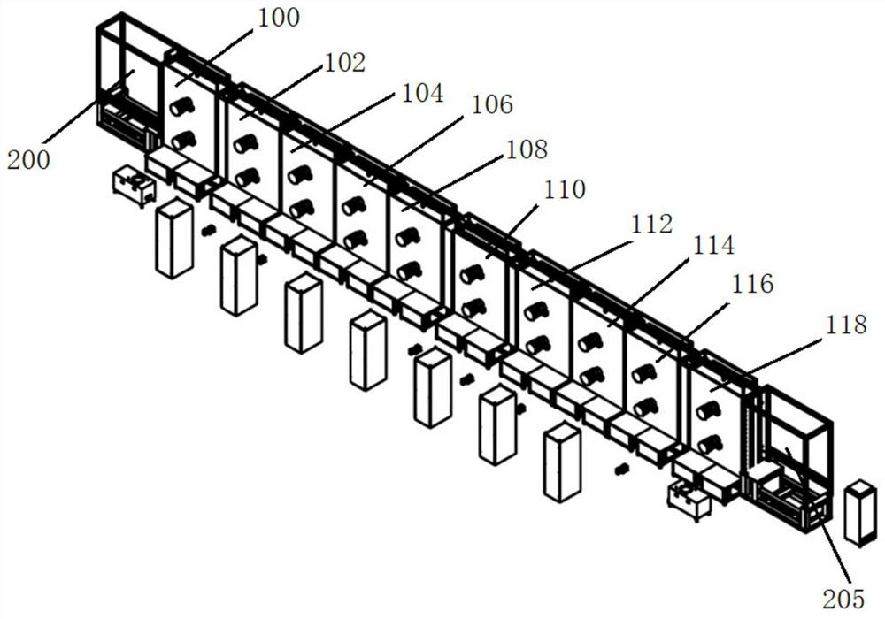
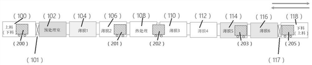
[0184] K1), select Ti (thickness 1mm) as base material, base material has flexibility, the background vacuum degree of vacuum system is 1 * 10 - 4 Pa, after the cleaned base material is fixed on the first movable frame (200), enter the high-vacuum vacuum feeding chamber (100) together, and enter the film 2 ( 106);

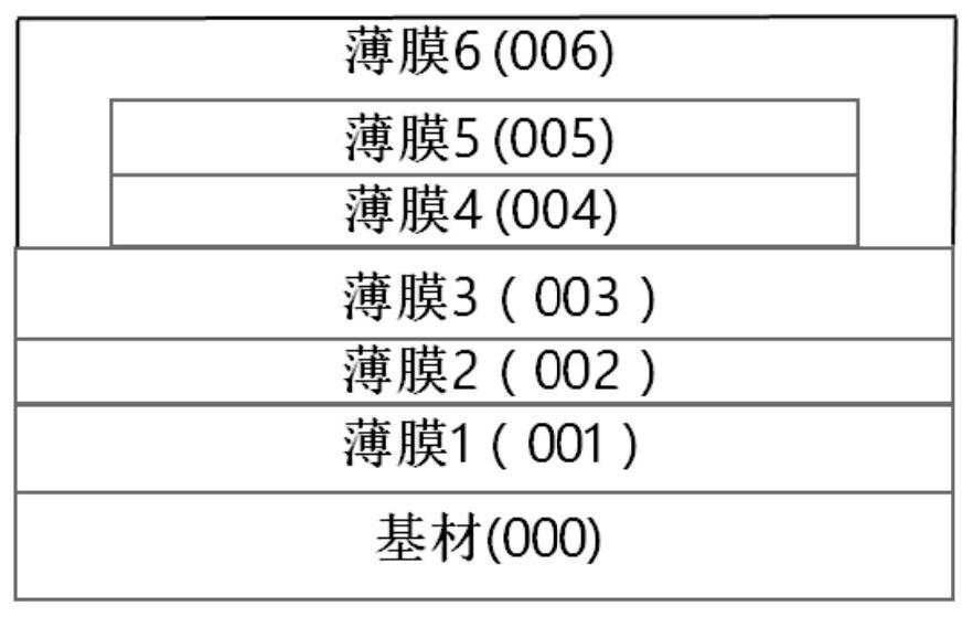
[0185] K2), in thin film 2 chamber (106), deposit thin film 2 as battery positive pole, positive pole is LiMn 2 o 4 , thickness 2000nm;

[0186]K3), in the heat treatment chamber (108), the substrate and the film are subjected to 800°C vacuum heat treatment;

[0187] K4), in film 3 chamber (110), deposit film 3, as battery electrolyte, electrolyte is lithium lanthanum zirconium oxygen (LLZO), thickness 3000nm;

[0188] K5), in thin film 4 chamber (112), deposit thin film 4, as battery negative pole, negative pole is Si, and thickness i...

Embodiment 2

[0193] Embodiment 2 Flexible lithium-free negative electrode type-manufacture of all-solid-state thin-film lithium battery, combined with Figure 10 and Figure 11 Shown:

[0194] J1), polyimide PI foil (thickness 10μm) is selected as the substrate, the substrate is ultra-thin and flexible, and the background vacuum of the vacuum system is 1×10 -4 Pa, after fixing the cleaned substrate on the first movable frame (200), enter the high-vacuum vacuum feeding chamber (100) together, and enter the pretreatment chamber through the first vacuum valve (101). (102);

[0195] J2), in the pretreatment chamber (102), use the ion source to perform ion bombardment cleaning and activation on the surface of the substrate;

[0196] J3), in the thin film 1 chamber (104), deposit thin film 1 to the base material, as battery anode current collector, material is aluminum, thickness 200nm;

[0197] J4), in thin film 2 chamber (106), deposit thin film 2, as battery positive electrode, positive e...

Embodiment 3

[0219] Example 3: Fabrication of Rigid Electrochromic Glass

[0220] combine Figure 12 and Figure 13 As shown, the steps of utilizing the above steps to manufacture electrochromic glass include the following:

[0221] (M1) Choose ordinary soda-lime ultra-thin glass (thickness 700 μm) as the substrate, and the background vacuum of the vacuum system is 1×10 -4 Pa, fix the cleaned substrate on the first movable frame (200), and enter the high-vacuum vacuum feeding chamber (100) together, and enter the film chamber 1 through the first vacuum valve (101). In the chamber (104), a thin film 1, ITO, is deposited on the substrate, with a thickness of 500nm, a heating temperature of 300°C, and a sheet resistance of 10 ohms / square;

[0222] (M2) in film 2 chamber (106), deposit film 2, WO 3 , as a glass color-changing layer with a thickness of 300nm; in the same chamber, deposit a Li film with a thickness of 50nm;

[0223] (M3) In the heat treatment chamber (108), the substrate an...


PUM

PropertyMeasurementUnit
thicknessaaaaaaaaaa
thicknessaaaaaaaaaa
thicknessaaaaaaaaaa

Abstract

The invention provides continuous vacuum coating production equipment and a production method thereof. The production equipment comprises a plurality of coating process chambers connected linearly, atleast one conveying device and at least one control device. The conveying devices are used for conveying base materials to pass through the coating process chambers. The control device is used for controlling the conveying devices to move between the coating process chambers according to a preset control program and controlling the coating process chambers to conduct film coating on the base materials conveyed into the chambers according to the control program. According to the continuous vacuum coating production equipment, the coating process chambers are designed into linear structure connection; the continuous vacuum coating production equipment is used for one-time vacuum forming of products such as solid-state ultrathin lithium batteries and color change and switchable glass and used for modular increasing / decreasing / sequence exchange of the coating process chambers. Therefore, through the continuous vacuum coating production equipment and the production method thereof providedby the invention, the good consistency, repeatability and stability of functional thin film products can be achieved.

Description

technical field [0001] The invention relates to the technical fields of all-solid-state lithium battery, color-changing glass and vacuum coating, in particular to a continuous vacuum coating production equipment and a production method thereof. Background technique [0002] The continuous coating system is widely used in the production of liquid crystal displays, touch screens, and building curtain wall glass. Its main feature is the use of large-area flat glass coatings to achieve continuous production on the assembly line, with good film uniformity and composition consistency. [0003] In recent years, a new type of battery product—all-solid-state thin-film lithium battery has the characteristics of high energy density, long cycle life, and high safety. It has become one of the important alternatives for the next generation of lithium-ion batteries and is used in smart cards, chips , flexible wearable devices, medical and health equipment. [0004] Another new type of pro...

Claims


Application Information

Patent Timeline
Patent Type & Authority Applications(China)
IPC IPC(8): C23C14/56
CPCC23C14/568
Inventor 陈牧
Owner 陈牧
Why Eureka
Try Eureka