Novel knee joint prosthesis with locking mechanism
A knee joint prosthesis and a new type of technology, applied in the field of knee joint prostheses, can solve the problems of decreased strength, reduced service life, damage to tibial pads, etc., and achieve the effects of increased contact area, increased connection strength, and tight connection
- Summary
- Abstract
- Description
- Claims
- Application Information
AI Technical Summary
Problems solved by technology
Method used
Image
Examples
Embodiment 1
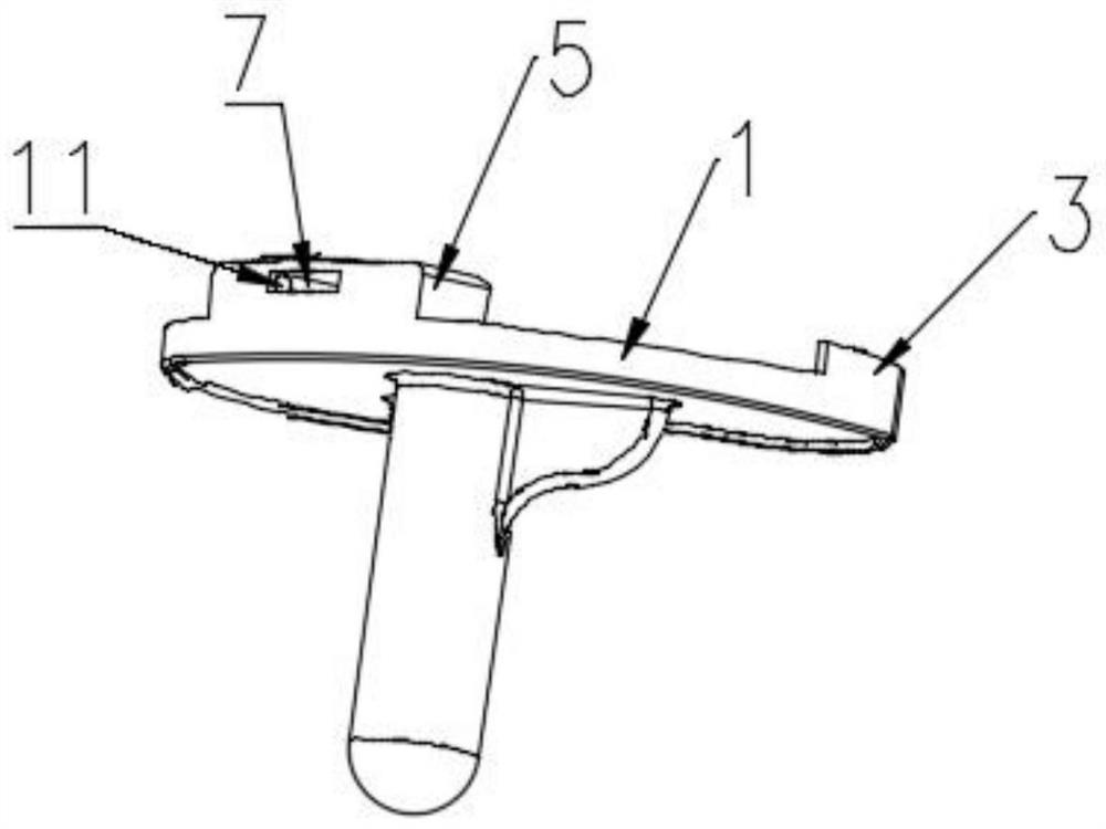
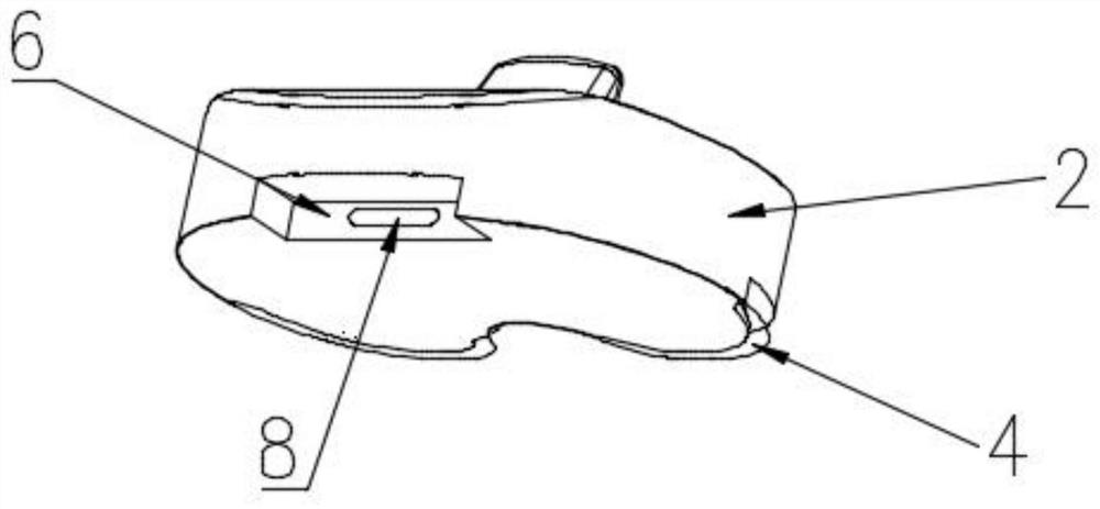
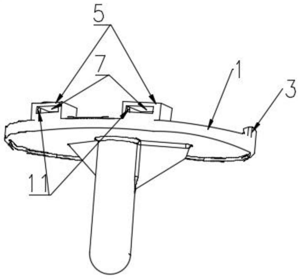
[0026] Example 1: Please refer to figure 1 , 2 , 5, 6, 7, use titanium alloy materials to prepare a knee joint prosthesis with a new type of locking mechanism, including tibial plateau support 1, tibial plateau support 1 is provided with a tibial spacer 2 on the upper end, and tibial plateau support 1 is provided on the upper end side There is a dovetail groove 3, the tibial spacer 2 and the dovetail groove 3 are provided with dovetail protrusions 4 at the corresponding positions, the tibial platform support 1 is provided with a square protrusion 5 at the end opposite to the dovetail groove 3, and the tibial spacer 2 A square groove 6 is provided at a position corresponding to the square protrusion 5, a rectangular hole 7 is provided in the square protrusion 5, an oblong hole 8 and a rectangular hole 7 are provided in the square groove 6 at a position corresponding to the rectangular hole 7 And an interposing piece 9 is provided in the oblong hole 8.
[0027] There is one square...
Embodiment 2
[0031] Example 2: Please refer to figure 1 , 2 , 5, 6, 7, use cobalt-chromium-molybdenum alloy materials to prepare a knee joint prosthesis with a new type of locking mechanism, including a tibial plateau support 1, a tibial spacer 2 is provided on the upper end of the tibial plateau support 1, and a tibial plateau support 1 The side is provided with a dovetail groove 3, the tibial spacer 2 and the dovetail groove 3 are provided with a dovetail bulge 4, the tibial platform support 1 is provided with a square bulge 5 at the end opposite to the dovetail groove 3. 2 is provided with a square groove 6 at a position corresponding to the square protrusion 5, a rectangular hole 7 is provided in the square protrusion 5, an oblong hole 8 is provided in the square groove 6 at a position corresponding to the rectangular hole 7, and a rectangular shape The hole 7 and the oblong hole 8 are provided with an interposer 9.
[0032] There is one square protrusion 5, square groove 6, rectangular ...
Embodiment 3
[0036] Example 3: Please refer to figure 1 , 2 , 5, 6, 7, use PEEK material to prepare a knee joint prosthesis of a new type of locking mechanism, including a tibial plateau support 1, the tibial plateau support 1 is provided with a tibial spacer 2 at the upper end, and the upper end of the tibial plateau support 1 is provided with The dovetail groove 3, the tibial spacer 2 and the dovetail groove 3 are provided with dovetail bulges 4 at the corresponding positions, the tibial platform support 1 is provided with a square bulge 5 at the end opposite to the dovetail groove 3, and the tibial spacer 2 and The position corresponding to the square protrusion 5 is provided with a square groove 6, the square protrusion 5 is provided with a rectangular hole 7, and the position corresponding to the rectangular hole 7 in the square groove 6 is provided with an oblong hole 8, rectangular hole 7 and An inner insert 9 is provided in the oblong hole 8.
[0037] There is one square protrusion 5...
PUM
| Property | Measurement | Unit |
|---|---|---|
| Width | aaaaa | aaaaa |
| Thickness | aaaaa | aaaaa |
| Width | aaaaa | aaaaa |
Abstract
Description
Claims
Application Information
 - R&D
- Intellectual Property
- Life Sciences
- Materials
- Tech Scout
- Unparalleled Data Quality
- Higher Quality Content
- 60% Fewer Hallucinations
Browse by: Latest US Patents, China's latest patents, Technical Efficacy Thesaurus, Application Domain, Technology Topic, Popular Technical Reports.
© 2025 PatSnap. All rights reserved.Legal|Privacy policy|Modern Slavery Act Transparency Statement|Sitemap|About US| Contact US: help@patsnap.com


