Medical decompression drainage device based on stomach intestine, pleuroperitoneal cavity and postoperative parts

A technology of decompression drainage and thoracoabdominal cavity, which is applied in the field of medical equipment, can solve problems such as unintuitive suction pressure, occupational exposure or infection of medical staff, and uneven pressure, so as to avoid medical safety hazards, facilitate medical measures, and improve application sexual effect

Pending Publication Date: 2020-09-04
XIAN CHILDRENS HOSPITAL
View PDF5 Cites 0 Cited by
  • Summary
  • Abstract
  • Description
  • Claims
  • Application Information

AI Technical Summary

Problems solved by technology

[0005] 1. The pressure of suction is not intuitive, and the pressure cannot be adjusted freely according to different types of patients;
[0006] 2. If the drainage pipe is bent, the drainage will be blocked and the drainage will not be smooth, which is not easy to be found, and may cause adverse consequences;
[0007] 3. The drainage tube in contact with the patient's skin and mucous membrane may cause the tube to cling to the mucous membrane wall due to the large negative pressure, resulting in local mucous membrane wall ischemia, necrosis, and mucous membrane wall damage;
[0008] 4. The drainage process requires continuous observation by medical staff or patients, and untimely observation may cause adverse consequences;
[0009] 5. When the drainage device is squeezed twice or multiple times,

Method used


Image

  • Medical decompression drainage device based on stomach intestine, pleuroperitoneal cavity and postoperative parts
  • Medical decompression drainage device based on stomach intestine, pleuroperitoneal cavity and postoperative parts
  • Medical decompression drainage device based on stomach intestine, pleuroperitoneal cavity and postoperative parts

Examples


Embodiment 1

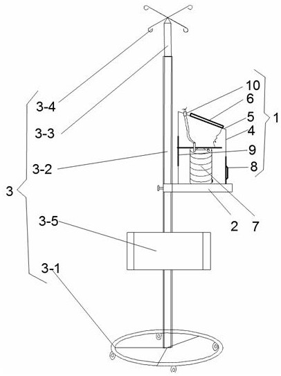
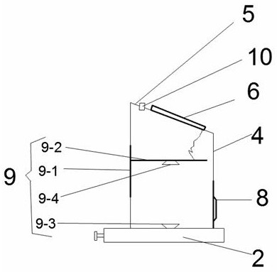
[0039] This embodiment provides a medical decompression and drainage device based on the gastrointestinal tract, thoracoabdominal cavity, and postoperative parts. Please refer to figure 1 and figure 2 as shown, figure 1 It is a structural schematic diagram of the medical decompression and drainage device of the present invention, figure 2 It is a schematic diagram of the driving device of the medical decompression and drainage device. In this embodiment, the decompression and drainage device includes a driving device 1, and the driving device 1 is detachably arranged on the bracket body 3 through the base 2. The driving device 1 includes a cylindrical shell The body 4 is provided with an inclined slope 5 on the top surface of the housing 4, and a control panel 6 is arranged on the inclined slope 5.

[0040] Wherein, an elastic flow guide 7 is detachably fixed on the inner bottom wall of the housing 4, and the elastic flow guide 7 expands and contracts in the height directi...

Embodiment 2

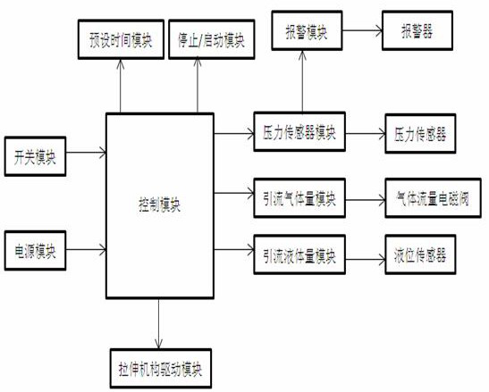
[0047] This embodiment is further improved on the basis of embodiment 1, as image 3 As shown, in order to improve the intelligence of the decompression and drainage device, the control panel 6 of this embodiment includes a display screen and several operating modules. A preset time module, a pressure sensor module, a start / stop module, a drainage gas volume module, a drainage liquid volume module, a stretching mechanism driving module, and several sensor modules are electrically connected.

[0048] As a further optimization of the sensor module of this embodiment, the sensor module includes a pressure sensor module, a drainage liquid sensor module, and a drainage gas flow module. The output end of the pressure sensor module is electrically connected with the pressure sensor located in the elastic diverter. The output end of the liquid level sensor module is electrically connected with the liquid level sensor located in the elastic diverter. The drainage gas flow module is e...

Embodiment 3

[0051] This embodiment is further improved on the basis of embodiment 1 and embodiment 2, as Figure 4 As shown, the elastic drainer 7 is cylindrical, including the drainer top plate 7-1, the drainer bottom plate 7-2, the drainer top plate 7-1 and the drainer bottom plate 7-2 are hard plate structures, and the drainer The side of the top plate 7-1 is provided with a drainage tube 7-3 connected to the drainage tube at the human body side, and the drainage tube 7-3 is drawn out through the circular through hole 10 on the inclined slope, and is connected with the drainage tube at the patient side.

[0052] A bellows-shaped cylindrical bottle body 7-4 made of medical rubber material is provided between the drainer bottom plate 7-2 and the drainer top plate 7-1, and the cylindrical bottle body 7-4 is placed between the cylindrical bottle body 7-4. Stretches in the height direction.

[0053] In order to reduce the generation of medical waste and improve the reutilization rate of th...


PUM


Abstract

The invention provides a medical decompression drainage device based on stomach intestine, pleuroperitoneal cavity and postoperative parts. The medical decompression drainage device comprises a driving device, wherein the driving device is detachably arranged on a bracket body through a base and comprises a cylindrical casing, an inclined surface is formed on the top surface of the casing, and a control panel is arranged on the inclined surface; an elastic drainage device is detachably fixed to the bottom wall in the casing, a side door is arranged on the side, away from the bracket body, of the casing and serves as an entrance of the elastic drainage device; a stretching mechanism is arranged at the upper part in the casing, the lower end of the stretching mechanism is connected with theupper end of the elastic drainage device, the control panel controls the stretching mechanism to stretch the elastic drainage device, so that negative pressure is produced in the elastic drainage device, a constant negative pressure state is kept, and the risk of reflux infection is avoided. The decompression drainage device is safe, reliable and convenient to use, the amount of gas and fluid drained out of the body can be displayed on the control panel in real time, and reliable and accurate judgment basis is provided for medical effects.

Description

technical field [0001] The invention relates to the technical field of medical devices, in particular to a medical decompression drainage device based on gastrointestinal, thoracic and abdominal cavity, and postoperative parts. drainage. Background technique [0002] Generally speaking, fluid and gas will be produced in the patient's surgical site or gastrointestinal tract after surgery, and the gas and liquid accumulated in the patient's body need to be discharged in time to reduce the pressure in the gastrointestinal tract and postoperative wound and reduce the risk of complications. occur. [0003] Postoperative drainage is a common medical care technology, which uses the principle of negative pressure suction to discharge the gas and liquid accumulated in the patient's body through a drainage device. Patients with different types and different surgical sites have different postoperative drainage conditions. Some patients have more gas and liquid in their bodies, while ...

Claims


Application Information

Patent Timeline
IPC IPC(8): A61M1/00
CPCA61M1/0011A61M1/0023A61M2205/18A61M1/74A61M1/84
Inventor 李强
Owner XIAN CHILDRENS HOSPITAL
Why Eureka
Try Eureka