Redundant mechanical arm based on tensegrity structure

A technology of tensioning the overall structure and mechanical arm, applied in the field of robotics, can solve the problems of small movement range and slow response speed, and achieve the effect of large movement range, small structural inertia force, and fast structural response speed.

Active Publication Date: 2020-09-04
SHANDONG UNIV
View PDF9 Cites 2 Cited by
  • Summary
  • Abstract
  • Description
  • Claims
  • Application Information

AI Technical Summary

Problems solved by technology

The tensegrity structure retains the load-carrying capacity of rigid components and the deformation capacity of flexible components at the same time, and has the advantages of both rigid structure and soft structure. Favored, such as the Chinese patent document application number CN201810899370.1 proposed a tension floating flexible joint, but it has the disadvantages of slow response speed and small range of motion

Method used


Image

  • Redundant mechanical arm based on tensegrity structure
  • Redundant mechanical arm based on tensegrity structure
  • Redundant mechanical arm based on tensegrity structure

Examples


Embodiment 1

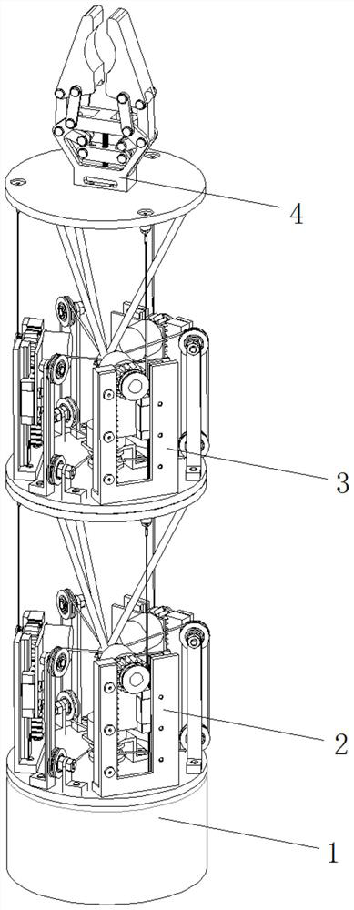
[0043] A redundant mechanical arm based on a tensegrity structure includes a base 1 , a first joint 2 , a second joint 3 , and grippers 4 .

[0044] The rotational connection between the base and the first joint forms a rotational degree of freedom.

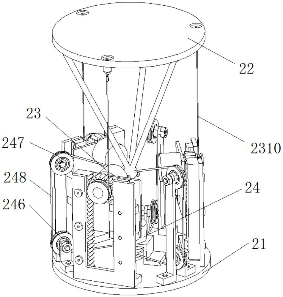
[0045] The structure of the first joint is the same as that of the second joint, which is a parallel joint based on the tensegrity structure. The joint includes a static platform 21, a dynamic platform 22, a cable, a driving part 23, and a stiffness adjustment part 24, such as figure 2 As shown, the driving part is set on the static platform, and the driving part is connected with the moving platform through the cable, and the driving part is used to drive the movement of the moving platform; the stiffness adjusting part is set on the static platform, and the stiffness adjusting part is connected with the moving platform through the cable, and the stiffness The adjusting part is used for adjusting the stiffness of the joint.

[0...

Embodiment 2

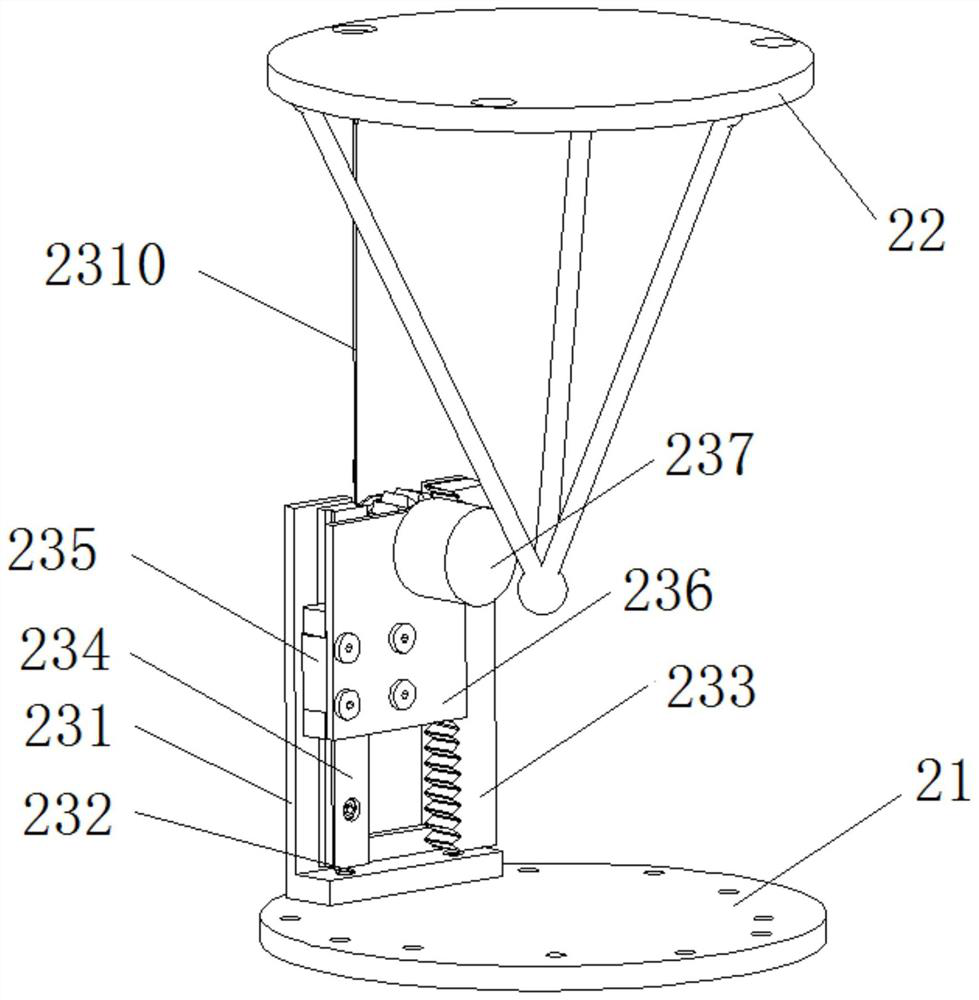
[0048] A kind of redundant manipulator based on the tensegrity structure, its structure is as described in embodiment 1, the difference is that the driving part includes angle seat A231, motor A237, such as Figure 3-5 As shown, the corner seat A is set on the static platform, the rack 233 and the guide rail 234 are symmetrically arranged on the corner seat A, the motor A237 is fixed on the motor mounting plate 236, the motor mounting plate is connected with the slider 235, and the slider is placed on the guide rail , the slider can move along the guide rail; the gear 239 and the pulley A238 are connected to the output shaft of the motor through a flat key, the gear and the rack are meshed, the pulley A is connected to one end of the cable A2310, and the other end of the cable A is connected to the moving platform. When the DC motor A rotates clockwise (facing the motor output shaft), it drives the pulley A to rotate, so that the cable A is wound on the pulley A, and then drive...

Embodiment 3

[0051] A redundant mechanical arm based on a tensegrity structure, its structure is as described in Embodiment 2, the difference is that the other end of the cable A is connected to the moving platform through the hanging code 2311 and locked by the lock A2312.


PUM


Abstract

The invention relates to a redundant mechanical arm based on a tensegrity structure, and belongs to the technical field of robots. The redundant mechanical arm comprises a base, a first joint, a second joint and a clamping jaw; the base is rotatably connected with the first joint to form the rotational freedom; structures of the first joint and the second joint are the same, joints comprise staticplatforms, movable platforms, inhaul cables, driving parts and rigidity adjustment parts, the driving parts are arranged on the static platforms, the driving parts are connected with the movable platforms through the inhaul cables, and the rigidity adjustment parts are used for adjusting the rigidity of the joints; and the movable platform of the first joint is fixedly connected with the static platform of the second joint, and the clamping jaw is arranged on the movable platform of the second joint. By combining the advantages of a rigid body structure and a soft body structure, the redundant mechanical arm based on the tensegrity structure has the advantages of light mass, high strength, good flexibility, high safety, flexible motion, large working space, high response speed and the like.

Description

technical field [0001] The invention relates to a redundant mechanical arm based on a tensioned integral structure, which belongs to the technical field of robots. Background technique [0002] Traditional manipulators can usually be divided into serial manipulators and parallel manipulators. The series manipulator is formed by a series of connecting rods connected in series through rotating joints or moving joints. It is an open kinematic chain robot, which has the advantages of simple structure, decoupling of motion between joints, and large working space; the parallel manipulator consists of an up and down motion platform It is composed of two or more motion branch chains, and one or more closed-loop mechanisms are formed between the motion platform and the motion branch chains, which have the advantages of high rigidity, high precision, and high speed. Both serial manipulators and parallel manipulators have their own characteristics and applicable occasions, and it is d...

Claims


Application Information

Patent Timeline
Patent Type & Authority Applications(China)
IPC IPC(8): B25J9/00B25J9/12
CPCB25J9/003B25J9/1035B25J9/104B25J9/12
Inventor 刘义祥周乐来柴汇宋锐李贻斌
Owner SHANDONG UNIV
Why Eureka
Try Eureka