Pneumatic cast iron pipe centrifugal casting machine mold braking device

A centrifugal casting machine, braking device technology, applied in drum brakes, brake types, brake actuators, etc., can solve the problem of reducing the service life of equipment and molds, the hidden dangers of the stability of the operation effect of the electromagnetic brake mechanism, and the shaft It can improve the operation efficiency and stability, the action mechanism is efficient and reliable, and the service life is prolonged.

Pending Publication Date: 2020-09-04
侯马市风雷管模制造股份有限公司
View PDF0 Cites 0 Cited by
  • Summary
  • Abstract
  • Description
  • Claims
  • Application Information

AI Technical Summary

Problems solved by technology

However, the friction part between the driving roller and the cast pipe mold is the "roller table" part of the cast pipe mold. Long-term friction will cause stress damage on the surface of the cast pipe mold, so that the mold rotates at a high speed in the "casting" state. The beating is intensified, which not only reduces the service life of equipment and molds, but also indirectly affects the quality of centrifugal casting pipes
[0004] 2. The effective mechanism of electromagnetic brake braking has high conduction loss, complex structure, and cumbersome on-site debugging
[0005] 3. The on-site environment of centrifugal casting of cast iron pipes is relatively harsh, high temperature, high humidity, and metal powder lead to hidden dangers in the stability of the operation effect of the electromagnetic brake mechanism

Method used


Image

  • Pneumatic cast iron pipe centrifugal casting machine mold braking device

Examples


Embodiment 1

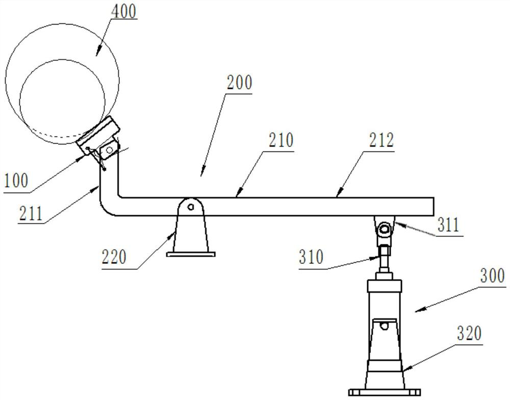
[0023] Such as figure 1 As shown, a pneumatic cast iron pipe centrifugal casting machine mold brake device includes a brake metal block 100 for directly acting on the outer surface of the cast pipe mold 400 to brake it, a brake transmission part 200 and a brake Power part 300, one end of the brake transmission part 200 is connected to the brake metal block 100, and the other end is connected to the brake power part 300; the brake metal block 100 is in contact with the outer surface of the cast pipe mold 400 Direct contact and friction reduce the dedicated speed of the cast pipe mold 400. The braking transmission part 200 acts as a force transmission during the braking action, and the braking power part 300 is used to provide power for the braking action of the mold 400. ;

[0024] The brake transmission part 200 includes a transmission lever 210 and a lever support 220, the transmission lever 210 is installed on the lever support 220 through a pin shaft, and the "pin shaft" s...

Embodiment 2

[0029] Based on the structure of Embodiment 1, in Embodiment 2, the length direction of the horizontal rod 212 of the transmission lever 210 and the length direction of the vertical rod 211 form a 90° right angle, and the length of the horizontal rod 212 is greater than The length dimension of the vertical rod 211.

Embodiment 3

[0031] Based on the structure of Embodiment 1, in Embodiment 3, the distance between the trunnion cylinder 310 and the lever support 220 is much greater than the distance between the brake metal block 100 and the lever support 220, which can reduce the The force to be borne by the trunnion cylinder 310 during braking.


PUM


Abstract

The invention discloses a pneumatic cast iron pipe centrifugal casting machine mold braking device. The device comprises a brake metal block, a brake transmission part and a brake power part, whereinone end of the brake transmission part is connected with the brake metal block, and the other end of the brake transmission part is connected with the brake power part; the brake transmission part comprises a transmission lever and a lever supporting base, the transmission lever is mounted on the lever supporting base through a hinge pin, the transmission lever is of an L-shaped structure and comprises a horizontal rod and a vertical rod which are integrally formed, and the free end of the vertical rod is fixedly connected with the brake metal block located thereon; and the brake power part comprises a trunnion cylinder and a cylinder supporting base, the upper end of the trunnion cylinder is mounted on a lug plate at the tail part of a horizontal rod of the transmission lever through a hinge pin, and the trunnion cylinder is connected with the cylinder supporting base through a trunnion thereof. According to the device, targeted, simple and efficient braking can be carried out on a high-speed rotating cast pipe mold, abrasion of key parts of the cast pipe mold is reduced, and the service life of the cast pipe mold is prolonged.

Description

technical field [0001] The invention belongs to the technical field of centrifugal casting equipment for cast iron pipes, in particular to a mold braking device for a pneumatic centrifugal casting machine for cast iron pipes. Background technique [0002] The braking device of the traditional cast iron pipe centrifugal casting equipment is an electromagnetic brake type braking device for the main engine motor pulley. This type of braking device has the following disadvantages: [0003] 1. The brake-type braking method is to reduce the rotation speed of the driving supporting wheel by acting on the motor pulley, and then reduce the speed through friction between the driving supporting wheel at low speed and the high-speed rotating cast pipe mold. However, the friction part between the driving roller and the cast pipe mold is the "roller table" part of the cast pipe mold. Long-term friction will cause stress damage on the surface of the cast pipe mold, so that the mold rotates...

Claims


Application Information

Patent Timeline
IPC IPC(8): F16D49/00F16D65/14F16D121/04F16D121/14
CPCF16D49/00F16D65/14F16D2121/04F16D2121/14
Inventor 支喜发原相杰刘烨郝庆文
Owner 侯马市风雷管模制造股份有限公司
Why Eureka
Try Eureka