
A chip resistor

A chip resistor and resistor technology, applied in resistors, resistor terminals/electrodes, non-adjustable metal resistors, etc., can solve the short-circuit failure at both ends of the chip resistor, it is difficult to control the amount of solder liquid, the chip resistor Due to limited volume and other problems, it can reduce short-circuit phenomenon, improve stability and effectiveness, and reduce damage.

Active Publication Date: 2021-12-31
深圳市慧达云泰科技有限公司
View PDF7 Cites 0 Cited by
  • Summary
  • Abstract
  • Description
  • Claims
  • Application Information

AI Technical Summary

Problems solved by technology

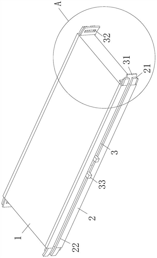
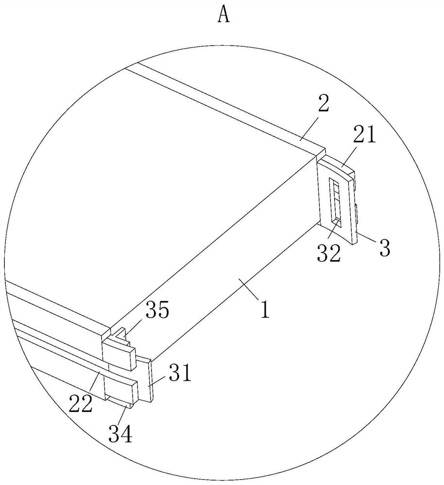
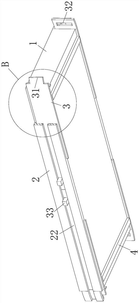
[0007] The technical solution adopted by the present invention to solve the technical problem is: a chip resistor, including a resistor body; two groups of concave-shaped slide plates are symmetrically connected to the two sides of the resistor body along its width direction, and the slide plate The ends are respectively provided with arc-shaped ends extending to the outer end of the resistor body, and the two symmetrical arc-shaped ends are respectively bent and deformed toward each other; the cavity formed by the slide plate and the side of the resistor body is respectively provided with a Symmetrically distributed metal flakes, the metal flakes can slide along the length direction of the resistor body under the limit of the slide plate, and at the same time, the outer end of the metal flakes can be attached to the side wall under the action of the arc-shaped end when it moves bending deformation; and the outer ends of one row of metal sheets are provided with engaging parts, while the outer ends of the other row of metal sheets are provided with engaging grooves that match the engaging parts; the outer ends of the metal sheets are respectively When the direction of the resistor body moves, the engaging parts and engaging grooves on the two adjacent metal sheets can engage with each other and form a solder cavity for welding; when working, when targeting a larger chip resistor, such as When the type of resistor is 2512, it is difficult for workers to control the amount of solder liquid in the process of soldering the chip resistor. When the solder liquid is used more, it will not only cause the waste of solder liquid, but also easily lead to one end of the chip resistor. When fixing, part of the solder liquid is squeezed to the other end, and due to the limited volume of the chip resistor, it is difficult for workers to observe this detail, which eventually leads to short circuit failure at both ends of the chip resistor; and when the solder liquid is used less, Due to the limited welding level of some workers, the soldering area of ​​the chip resistor is insufficient, which makes the welding between the electrode of the chip resistor and the solder joint unreliable, and then it is prone to open circuit phenomenon, which affects the working quality and service life of the chip resistor; When the chip resistor in the invention is working, a slide plate and a metal sheet that can slide under the action of the slide plate are arranged symmetrically on the side of the resistor body. When the chip resistor is in an unwelded state, the position between the slide plate and the resistor body The metal flakes between them can be effectively protected, reducing the damage and deformation of the metal flakes caused by external mechanical collisions and extrusions, so that the metal flakes can work effectively and stably in the subsequent welding process; when the resistor body When the two ends need to be welded with the solder joints on the connection board such as the PCD board, at this time, apply force to the outer ends of the metal sheet and slide the ends away from the resistor body, so that the end of the metal sheet is in the arc. Under the action of resistance and extrusion of the shaped end, the bending deformation is carried out in the direction of the adjacent row of metal sheets, so that the adjacent two metal sheets slide out from the inside of the slide plate while leaning against each other until the engaging part on the metal sheet can move to the The position of the engaging groove on the other metal sheet is matched with it, so that the two mated metal sheets can form a solder cavity for welding the resistor body. At this time, connect the solder cavity at both ends of the resistor body to the connecting plate The solder joints are aligned and attached, and then the solder liquid is dripped into the solder cavity at both ends of the resistor body and the cavity is filled, so that the solder liquid filled in the cavity can cool the resistor body The electrodes at both ends are connected to the solder joints. At this time, the resistance body is welded through the set solder cavity, which not only effectively controls the amount of solder liquid, reduces the waste of solder liquid and poor welding of the resistance body, but also can prevent the solder liquid The position is effectively limited, reducing the solder liquid at one end of the resistor body from flowing into the other end of the resistor body and causing the short circuit of the resistor patch, thus greatly improving the stability and effectiveness of the chip resistor during welding and use

Method used


Image

  • A chip resistor
  • A chip resistor
  • A chip resistor

Examples


Embodiment approach

[0026] As an embodiment of the present invention, the bottom end of the resistor body 1 is symmetrically bonded with a strip-shaped protective strip 4 along its length direction, and the protective strip 4 is made of elastic silicon rubber material; when working, when When the connecting plate welded with the resistor body 1 is uneven, the solder liquid inside the solder cavity 5 is easy to flow out from the gap between the bottom of the solder cavity 5 and the connecting plate, so that it is easy to make the solder liquid from the solder cavity 5 The outflowing solder liquid flows into the solder cavity 5 at the other end of the resistor body 1 and a short circuit occurs. At this time, a silicone rubber protective strip 4 that can withstand a certain high temperature is installed at the bottom of the resistor body 1, so that the protective strip 4 is on the resistor body. 1 can be tightly attached to the uneven connecting plate, so that the protective strip 4 can effectively s...


PUM


Abstract

The invention belongs to the technical field of resistors, specifically a chip resistor, including a resistor body; two groups of concave-shaped slide plates are symmetrically connected to the two sides of the resistor body, and the ends of the slide plates are respectively provided with arc-shaped ends. The cavity formed by the sliding plate and the side of the resistor body is respectively provided with symmetrically distributed metal sheets; and the outer end of one row of metal sheets is provided with a snap-fitting portion, while the outer end of the other row of metal sheets is provided with a card. The joint part is matched with the engaging groove; the present invention welds the resistor body by setting a solder cavity composed of metal sheets, which not only effectively controls the amount of solder liquid, reduces the waste of solder liquid and poor welding of the resistor body, but also It can effectively limit the position of the solder liquid and reduce the short circuit phenomenon of the resistance body during welding, thus greatly improving the stability and effectiveness of the chip resistance during welding and use.

Description

technical field [0001] The invention belongs to the technical field of resistors, in particular to a chip resistor. Background technique [0002] SMD resistor, also known as chip fixed resistor, is a kind of metal glass glaze resistor; SMD resistor is a resistor made by mixing metal powder and glass glaze powder and printing on the substrate by screen printing method. It has It is resistant to humidity and high temperature, and has a small temperature coefficient, which can greatly save the cost of circuit space, thus making the design more refined. [0003] The current steps of soldering chip resistors: First, heat and melt the solder to a solder spot on the PCB board, then use a clip to place the electrode at one end of the chip resistor on the solder spot where the solder remains, and align the other electrode with the PCB Another solder joint on the board; then use a welding torch to melt the solder on the solder joint and press down on both ends of the chip resistor to...

Claims


Application Information

Patent Timeline
Patent Type & Authority Patents(China)
IPC IPC(8): H01C1/02H01C1/14H01C7/00
CPCH01C1/02H01C1/14H01C7/00
Inventor 孙文程业品
Owner 深圳市慧达云泰科技有限公司
Learn More