Closed crankcase ventilation systems for heavy-duty engine systems and heavy-duty engine systems

A technology for engine system and crankcase ventilation, which is applied in the direction of crankcase ventilation, engine components, machines/engines, etc. It can solve the problems affecting the efficiency of the supercharger, excessive oil carrying capacity, and pollution of the supercharger, so as to improve efficiency and The service life, the effect of improving the uneven air supply, and the effect of reducing the risk of failure

Active Publication Date: 2021-08-13
ZHEJIANG GEELY NEW ENERGY COMML VEHICLES CO LTD +3
View PDF24 Cites 0 Cited by
  • Summary
  • Abstract
  • Description
  • Claims
  • Application Information

AI Technical Summary

Problems solved by technology

The internal volume of the heavy-duty methanol engine is large and complex, and the exhaust gas flow in the crankcase is uneven, which may easily cause emulsion accumulation in the unsmooth parts of the engine (inside the flywheel housing, the dead zone of the cylinder head cover), and it is easy to form sludge for a long time, that is, it is easy to cause pipe Road blockage, sludge deposition and other problems
At the same time, the national VI emission requirements are strict, and the amount of engine oil carried exceeds the standard, which cannot meet the requirements. Exceeding the standard of engine oil particles is very likely to cause pollution to the supercharger, affect the efficiency of the supercharger, pollute the supercharger, and corrode the intercooler And it is easy to cause spark plug carbon deposits and engine knocking and other problems

Method used


Image

  • Closed crankcase ventilation systems for heavy-duty engine systems and heavy-duty engine systems
  • Closed crankcase ventilation systems for heavy-duty engine systems and heavy-duty engine systems
  • Closed crankcase ventilation systems for heavy-duty engine systems and heavy-duty engine systems

Examples


Embodiment Construction

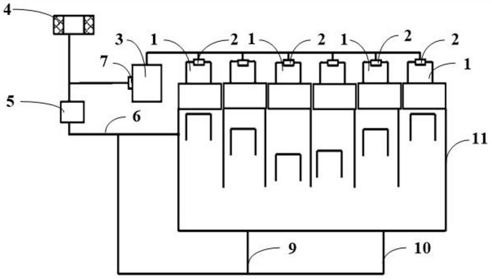
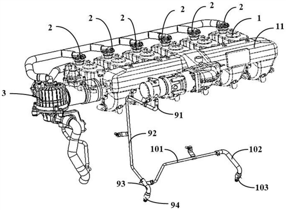
[0035] figure 1 A schematic schematic diagram of a closed crankcase ventilation system for a heavy duty engine system according to one embodiment of the invention is shown. figure 2 A schematic structural diagram of a closed crankcase ventilation system of a heavy-duty engine system according to an embodiment of the present invention is shown. The closed crankcase ventilation system is used on heavy duty diesel vehicles such as figure 1 and figure 2 As shown, the heavy duty diesel vehicle includes an air filter 4 , a traction control system 5 (TC), an intake manifold 6 and a PVC valve 7 . The closed crankcase ventilation system comprises at least one engine cylinder head cover 1 , at least one first oil-air separator 2 and a second oil-air separator 3 .

[0036] Each engine head cover 1 is arranged on an engine head of a heavy-duty engine system. Each first oil-air separator 2 is integrated inside an engine cylinder head cover 1, and is used for preliminary separation of...


PUM


Abstract

The invention provides a closed crankcase ventilation system of a heavy-duty engine system and the heavy-duty engine system. The closed crankcase ventilation system includes at least one engine head cover, each of said engine head covers being disposed on a respective engine head of a heavy-duty engine system, the interior of each said engine head cover being A first oil-gas separator is integrated, which is used for preliminary separation of the high-temperature oil gas entering the crankcase after combustion in the engine cylinder or the mixed oil-gas mixed with the high-temperature oil gas and fresh air; the second oil-gas separator, the The second oil-gas separator communicates with each of the first oil-gas separators, and is used to re-separate the oil and gas that has been initially separated by the first oil-gas separator, and the gas outlet of the second oil-gas separator is connected to the intake pipeline of the engine connected. The proposal of the invention can reduce the risk of failure of the second oil-gas separator, and improve the effect of uneven gas supply inside the large crankcase of the heavy-duty engine.

Description

technical field [0001] The invention relates to the technical field of heavy-duty vehicles, and oil and gas relate to a closed crankcase ventilation system of a heavy-duty engine system, a heavy-duty engine system and a heavy-duty diesel vehicle. Background technique [0002] At present, due to the technical development of the curved ventilation system of heavy-duty diesel engines in the market, the crankcase emissions of the National V stage are not included in the emissions of the whole machine. Most diesel engines use an open curved ventilation system. The design requirements are very low, and the maximum oil carrying capacity is less than 5g / h to meet the design requirements. After the country VI, the crankcase emission requirements will be tightened. For the closed crankcase ventilation system, the amount of oil carried should be controlled within 0.5g / h. There are also a small number of National VI diesel engines that use an open crankcase ventilation system, which re...

Claims


Application Information

Patent Timeline
Patent Type & Authority Patents(China)
IPC IPC(8): F01M13/04F01M13/02
CPCF01M13/028F01M13/04
Inventor 卢瑞军蔡文远乔风林康世邦苏茂辉
Owner ZHEJIANG GEELY NEW ENERGY COMML VEHICLES CO LTD
Why Eureka
Try Eureka