Annular electric propeller driven by axial magnetic flux motor

A technology of axial magnetic flux and motor drive, applied in the direction of rotary propellers, propulsion components, ship propulsion, etc., can solve the problems of reducing system propulsion efficiency, intermediate transmission loss, and large space occupation, so as to save cabin space, The effect of high reliability and less space in the cabin

Pending Publication Date: 2020-09-08
珠海市汉图达科技有限公司
View PDF0 Cites 2 Cited by
  • Summary
  • Abstract
  • Description
  • Claims
  • Application Information

AI Technical Summary

Problems solved by technology

This propulsion method has the following problems: complex structure, many parts, high failure rate, large space occupation, and heavy weight; low propulsion efficiency: the motor and propeller are driven by gears, shafting and other components, and gear meshing produces energy loss. Bearings are usually sliding bearings, with high friction and high friction power consumption; the above transmission links generate intermediate transmission losses and reduce the propulsion efficiency of the system; the transmission gear meshes to generate vibration and cause noise. Secondly, water flows through the shafting and water After the lower attachment, turbulent flow is generated, and the propeller rotates in the turbulent flow, generating excitation and cavitation, and the bursting of the cavitation generates noise

Method used


Image

  • Annular electric propeller driven by axial magnetic flux motor
  • Annular electric propeller driven by axial magnetic flux motor
  • Annular electric propeller driven by axial magnetic flux motor

Examples


Embodiment 1

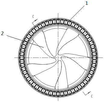
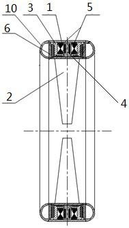
[0035] Embodiment 1: as figure 1 , 4 As shown in and 5, the annular electric propeller of this embodiment is a double-stator single-rotor assembly structure, which mainly includes: a housing, an axial flux motor, a propeller and a bearing assembly.

[0036] The axial flux motor of the present invention adopts an axial flux permanent magnet brushless motor (disc motor). The axial flux motor is different from the ordinary motor. The conductor system is placed radially, and the stator and rotor are disc structures. The motor is composed of a stator assembly, a rotor assembly, a casing, and an end flange. The left and right stator components are respectively fixed on the left and right end face flanges of the motor, and the middle is a single rotor component. The stator assembly of the motor is composed of an axial iron core and a coil, and can also be designed as a coreless structure. The stator assembly is encapsulated with multi-layer sealing and insulating filling protectio...

Embodiment 2

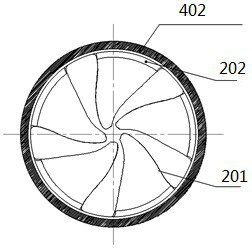
[0048] Example 2: When the power density requirement is not high, the type of single stator and single rotor can be used to reduce power and power density, such as Figure 6 and 7 As shown, the annular electric thruster of this embodiment has a single-stator and single-rotor assembly structure. The difference from Embodiment 1 is that the number of the stator assemblies is set as one group, and the rotor assembly is only driven by a single stator assembly on one side. With single stator and single rotor, the power is reduced and the power density is reduced, but the structure is simple and the cost is low, which is suitable for propellers with low power and low requirements on power density.

Embodiment 3

[0049] Embodiment 3: When the power needs to be larger and the diameter remains the same, that is, when the power density needs to be increased, it can be realized by increasing the number of stator assemblies and rotor assemblies, that is, multiple stator assemblies drive multiple rotor assemblies at the same time , multiple rotor assemblies simultaneously drive a propeller. Such as Figure 8 and 9 As shown, the annular electric propeller of this embodiment has a three-stator double-rotor assembly structure. The difference from Embodiments 1 and 2 is that three stator assemblies drive two rotor assemblies, and two rotor assemblies simultaneously drive a propeller.

[0050] The motor adopts a multi-disc structure with three stators and two rotors. The front and rear stator assemblies are respectively fixed on the front and rear end flanges of the motor, and the middle stator assembly is embedded in the housing. There is a rotor assembly in the middle of every two stator asse...


PUM


Abstract

The invention relates to an annular electric propeller driven by an axial magnetic flux motor. The annular electric propeller comprises a shell, the axial magnetic flux motor, a propeller and a bearing assembly. According to the annular electric propeller, the axial magnetic flux motor arranged in water is adopted to directly drive the propeller to rotate, intermediate transmission equipment is eliminated, and the rotor and the propeller assembly are supported by the bearing arranged in water and transmit thrust to the motor and a ship body; intermediate transmission loss between the motor andthe propeller is reduced, efficiency is improved, the structure of a propulsion system is simplified, and noise, vibration and the like are reduced.

Description

technical field [0001] The invention belongs to the technical field of marine turbine propellers, and in particular relates to an annular electric propeller driven by an axial magnetic flux motor. Background technique [0002] With the development of electric propulsion technology, electric propulsion systems are increasingly used on ships. Common electric propulsion systems include variable speed gearboxes, shafting (including shafts, couplings, various bearings and bearing housings, stern tube seals), propellers, etc.; , to drive the shafting and the propeller to rotate to generate thrust for the ship to move forward or backward. This propulsion method has the following problems: complex structure, many parts, high failure rate, large space occupation, and heavy weight; low propulsion efficiency: the motor and the propeller are driven by gears, shafting and other components, and the gear meshing produces energy loss. Bearings are usually sliding bearings, which have larg...

Claims


Application Information

Patent Timeline
Patent Type & Authority Applications(China)
IPC IPC(8): H02K16/04H02K1/18H02K1/27H02K5/04H02K5/16H02K7/09H02K7/14B63H1/14B63H21/17
CPCB63H1/14B63H21/17H02K1/182H02K1/2793H02K5/04H02K5/161H02K7/09H02K7/14H02K16/04
Inventor 郑锐聪邱湘瑶刘福超邵志江
Owner 珠海市汉图达科技有限公司
Why Eureka
Try Eureka