a skin reducer

A skin and slider technology, applied in the field of medical devices, can solve the problems of affecting the benign healing of wound skin, unable to grasp the effective pulling of the skin, limited pulling force and distance, etc., so as to facilitate disinfection and repeated use, save physical pain, The effect of improving satisfaction

Active Publication Date: 2022-04-29
THE SECOND XIANGYA HOSPITAL OF CENT SOUTH UNIV
View PDF0 Cites 0 Cited by
  • Summary
  • Abstract
  • Description
  • Claims
  • Application Information

AI Technical Summary

Problems solved by technology

However, because the tension-relieving thread itself has a certain degree of elasticity and has a certain cutting effect on the skin, the tension-relieving thread becomes loose under the long-term action of the tension on both sides of the skin wound, and cannot continuously provide effective tension relief for wound healing. Stretch support can not be adjusted according to the strength of the skin wound at any time, which will affect the benign healing of the wound skin and is not conducive to the reduction of skin scars
[0004] Or use tape to stick the skin or a patch to stick the skin, and use the sticking force to fix it on the skin around the wound so as to fix the skin. For wounds, the traction force and distance are limited, relying on tape sticking for a long time and soaking in disinfectant iodine solution when changing dressings in the later stage, the adhesive tape often falls off, and the tension-reducing traction fails
In addition, the stretching strength is not quantified, so it is impossible to grasp the best and effective stretching of the skin; moreover, when large skin or flap defects are caused by large skin wounds, it is often necessary to repair them by skin grafting or flap transplantation. The tension reducer often cannot satisfy the long-term, continuous, stable, and fine-tuned traction of the skin around the gap, so it cannot pull the skin around the gap with the gradual growth of the skin to close the skin gap. Therefore, clinically Currently commonly used skin tension devices and other stretching methods cannot meet the actual clinical individualized treatment needs

Method used


Image

  • a skin reducer
  • a skin reducer
  • a skin reducer

Examples


Embodiment Construction

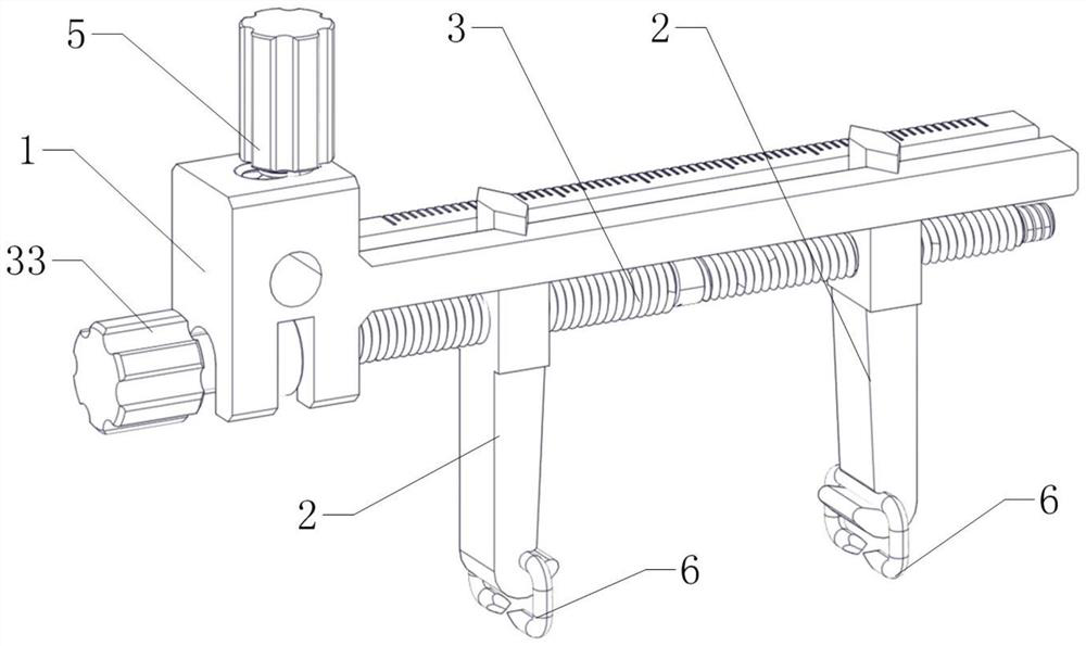
[0027] The core of the present invention is to provide a skin tension reducer, which can achieve quantitative traction, the traction force is continuous and stable, and the traction force on the skin is sufficient. There is a real clinical need for skin tension-reducing sutures.

[0028] In order to enable those skilled in the art to better understand the solution of the present invention, the present invention will be further described in detail below in conjunction with the accompanying drawings and specific embodiments.

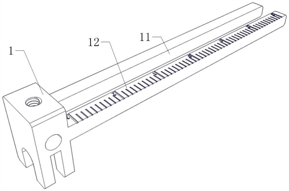
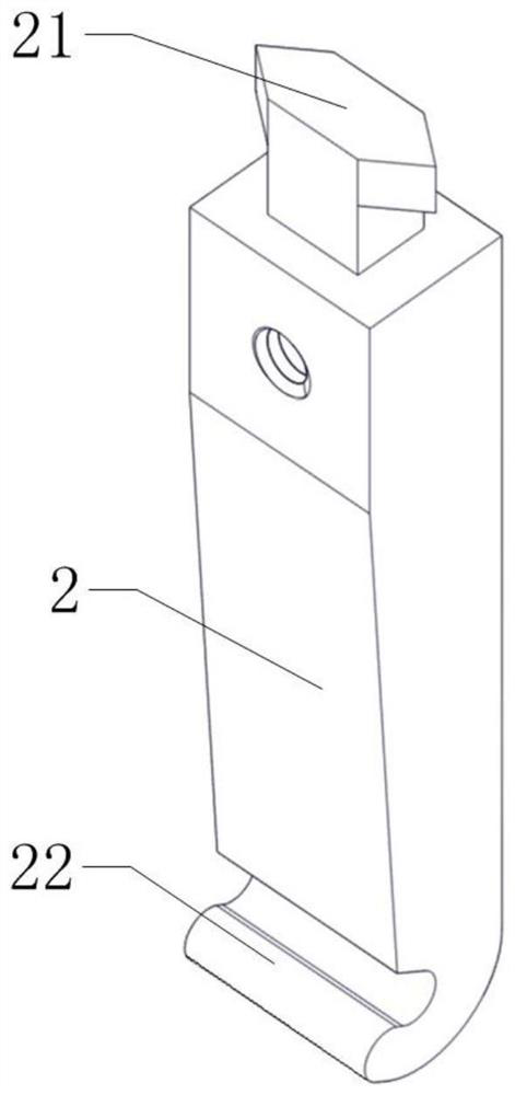
[0029] Please refer to Figure 1 to Figure 4 , figure 1 It is a structural schematic diagram of a specific embodiment of the skin tension reducer provided by the present invention; figure 2 It is a structural schematic diagram of the guide frame in a specific embodiment of the skin tension reducer provided by the present invention; image 3 A schematic structural view of the slider in a specific embodiment of the skin tension reducer provided by the pr...


PUM


Abstract

The invention discloses a skin tension reducer, which comprises a guide frame and two sliders, the two sliders are located on both sides of the skin wound, the extension direction of the guide frame is perpendicular to the extension direction of the sliders, and the guide frame is provided with The upper end of the slider is movably installed in the chute, the lower end of the slider is installed with a fixed needle that passes through the skin, and an adjusting screw is installed in parallel on the guide frame, and the adjusting screw is threaded to connect the slider to drive the two sliders. Blocks move closer or farther away from each other. The skin on both sides of the wound is fixed by the fixing pins at the lower ends of the two sliders, and then the distance between the two sliders is adjusted by adjusting the screw to adjust the traction distance. For patients with larger wounds and more skin defects, it can be quantified. , Stable, continuous and effective traction.

Description

technical field [0001] The invention relates to the field of medical devices, in particular to a skin tension reducer. Background technique [0002] Scar hyperplasia and secondary contracture deformity will cause physical and psychological harm to patients and reduce the quality of life of patients. The formation of surgical incision scar is affected by many factors, among which the local skin tension has a particularly significant impact on scar formation. An incision with high tension not only has a wider scar width after healing, but also is prone to scar hyperplasia and contracture. If a simple, effective, and non-invasive method of tension reduction is used in the early stage of skin incision suturing, the formation of scars can be reduced. [0003] At present, the commonly used suture method for skin wound tension reduction in clinical practice is to place tension-reducing sutures on the skin on both sides of the wound to complete the skin tension reduction requireme...

Claims


Application Information

Patent Timeline
Patent Type & Authority Patents(China)
IPC IPC(8): A61B17/08
CPCA61B17/08
Inventor 张杰张博友王李佳朱动明徐姣王静成
Owner THE SECOND XIANGYA HOSPITAL OF CENT SOUTH UNIV
Why Eureka
Try Eureka