Broaching machine

A technology of pull rod and bed, which is applied to broaching machines. In this field, it can solve the problems of cutting teeth with iron filings and impurities are not easy to remove, so as to prevent the broach from rusting, save manpower and material resources, and improve production efficiency and product quality.

Pending Publication Date: 2020-09-15
重庆秋虎机械制造有限公司
View PDF12 Cites 3 Cited by
  • Summary
  • Abstract
  • Description
  • Claims
  • Application Information

AI Technical Summary

Problems solved by technology

[0004] Aiming at the deficiencies in the prior art, the present invention provides a broaching machine, which solves the problem in the prior art that the cutting teeth are mixed with iron filings and impurities during the processing of the broaching machine and are difficult to remove

Method used


Image

  • Broaching machine
  • Broaching machine
  • Broaching machine

Examples


Embodiment Construction

[0013] The technical solutions in the present invention will be further described below with reference to the accompanying drawings and embodiments.

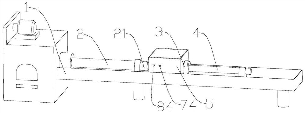
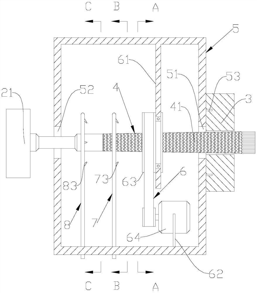
[0014] like figure 1 As shown, the embodiment of the present invention proposes a broaching machine, which includes a machine bed 1 and a piston rod 2 arranged on the machine bed 1. The piston rod 2 is fixedly connected with a follower tool rest 21 that clamps the broach 4, The front end of the follow-up tool rest 21 is also provided with a cleaning chamber 5, the upper and lower ends of the cleaning chamber 5 are opened up, the top opening is to facilitate the maintenance of the cleaning chamber 5 and the installation of other devices, and the bottom opening is to facilitate the outflow of cleaned impurities and iron filings; Both ends of the cleaning chamber 5 are provided with a knife inlet hole 51 and a knife outlet hole 52 for the broach 4 to pass through. The diameter of the knife inlet hole 51 and the knife hole 52 are bo...


PUM


Abstract

The invention provides a broaching machine, and particularly relates to the field of broaching machine equipment. The broaching machine comprises a machine bed and a piston pull rod arranged on the machine bed, wherein the piston pull rod is fixedly connected with a follow-up broach rest for clamping a broach, and the front end of the follow-up broach rest is further provided with a cleaning cabin; and the two ends of the cleaning cabin are provided with a broach inlet and a broach outlet for allowing the broach to penetrate through, a clamp fixing pin is arranged on one end face of the broachinlet of the cleaning cabin, and a ring brush device, a water spraying device and an air spraying device are sequentially arranged inside the cleaning cabin. The cleaning cabin deeply cleans the broach which finishes working, so that impurities and scrap iron on the broach are thoroughly removed, manpower and material resources for manual removal are saved, and the production efficiency and the product quality are also improved.

Description

technical field [0001] The invention relates to the field of broaching equipment, in particular to a broaching machine. Background technique [0002] A broaching machine is a machine tool that uses a broach as a tool to process through holes, planes and forming surfaces of workpieces. Broaching can obtain high dimensional accuracy and small surface roughness, high productivity, and is suitable for mass production. Most broaching machines use the hydraulic system set on the machine tool as the power equipment, clamp the broach with a clamp, and then perform the broaching work on the workpiece fixed on the bed. [0003] In the prior art, in the process of broaching the workpiece, the broach will pass through the machining hole of the workpiece, and the machining hole is formed by several cutting teeth on the broach. and impurities will be mixed in the cutting teeth, the existing technology does not have a good mechanical means to remove these impurities and iron filings, and...

Claims


Application Information

Patent Timeline
IPC IPC(8): B23D41/00B23D39/00B23Q11/00
CPCB23D41/00B23D39/00B23Q11/00
Inventor 蒋联洪傅昌亮
Owner 重庆秋虎机械制造有限公司
Why Eureka
Try Eureka