Material transferring device, drilling mechanism and processing center

A material and processing station technology, applied in the field of workpiece processing and manufacturing, can solve the problems of inability to continuous production, low efficiency, and stalled conveying devices, and achieve the effect of ensuring uninterrupted production, saving costs, and reducing space occupied

Pending Publication Date: 2020-09-18
JIANGSU UNIV OF TECH
View PDF0 Cites 1 Cited by
  • Summary
  • Abstract
  • Description
  • Claims
  • Application Information

AI Technical Summary

Problems solved by technology

[0003] In order to solve the technical problems of the lock workpiece production line in the prior art, when the workpiece is processed, the conveying device needs to stop, continuous production cannot be performed, and the efficiency is low. The present invention provides a material circulation device and a drilling mechanism to solve the above-mentioned technical problems question

Method used


Image

  • Material transferring device, drilling mechanism and processing center
  • Material transferring device, drilling mechanism and processing center
  • Material transferring device, drilling mechanism and processing center

Examples


Embodiment 1

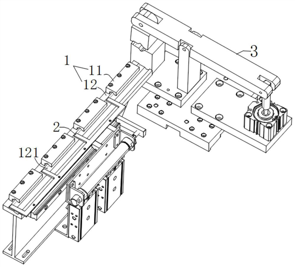
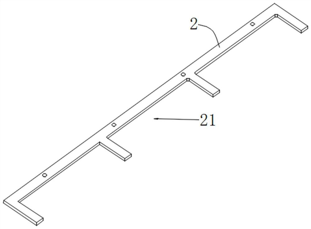
[0044] Such as Figure 1-9 As shown, the present embodiment provides a material circulation device, including a carrier body 1, a driving part 2 and a transfer module 3, wherein the carrier body 1 extends along the feeding direction, and a transfer area is arranged at the end of the feeding direction, and the driving part 2 Drive the workpiece to move along the carrier 1 to the transfer area, and then the transfer module 3 grabs the workpiece, and the transfer module 3 moves back and forth in a straight line between the transfer area and the processing station 4 to realize continuous and uninterrupted loading.

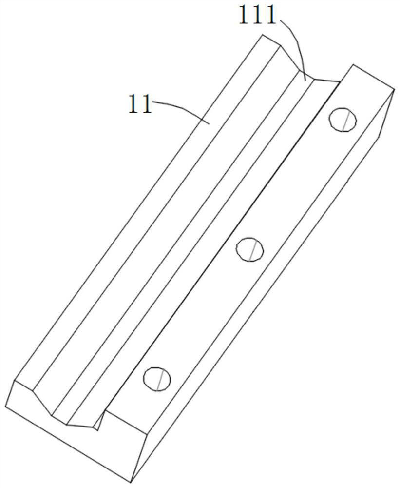
[0045] Preferably, the carrier 1 of this embodiment includes a guide plate 12 with a guide groove 121 on the guide plate 12, the workpiece is placed in the guide groove 121, and the workpiece will not deflect when the guide groove 121 is driven to move. The carrier 1 also includes a limiting block 11, which is fixedly mounted on the guide plate 12. The limiting block 1...

Embodiment 2

[0057] The present embodiment provides a drilling mechanism for processing lock cylinder holes, the drilling structure includes the above-mentioned material circulation device, the above-mentioned processing station 5 is configured as a drilling station, and the drilling station includes two opposite Arranged drilling machine, the drilling machine can drill holes on the lock core from both sides to form the gall hole of the lock core. In order to realize the continuous processing of the lock core bore, the drilling station in this embodiment is two and The layout is on both sides of the feeding direction. Each drilling station is equipped with a transfer module 3 correspondingly. The transfer module 3 is located between two opposite drilling machines. Further, the upstream and downstream directions of the transfer area are equipped with carriers. 1 and driving member 2, thereby realizing a drilling mechanism that can work continuously.

[0058] The previous station of the dril...


PUM


Abstract

The invention relates to the field of workpiece processing and manufacturing, in particular to a material transferring device, a drilling mechanism and a processing center. A material transferring device comprises a carrier, a drive member, a transferring module and a compressing part, wherein the carrier extends along a feeding direction, and the tail end of the carrier located in the feeding direction is provided with a transferring area; the drive member is used for driving a workpiece to move along the feeding direction; the transferring module is used for clamping the workpiece, the transferring module is configured to be installed linearly, and the transferring module moves between the transferring area and a processing station; the transferring module comprises a receiving part, andthe receiving part and a carrying surface of the carrier are on a same horizontal plane; and the compressing part is used for compressing and fixing the workpiece. According to the invention, the technical problems of impossible continuous production, low degree of automation and low efficiency when the workpiece is processed, a conveying device needs to be stopped in a lock workpiece productionline in the prior art.

Description

technical field [0001] The invention relates to the field of workpiece processing and manufacturing, in particular to a material circulation device, a drilling mechanism and a machining center. Background technique [0002] The lock core is the main part that controls the opening of the lock. It is the heart of the lock. It is the core part that can be rotated with the key and drives the lock bolt to move. It has extremely high precision requirements. The gall hole of the lock core is an important part of processing the lock core. , which uses the force of machine movement to pressurize the die to drill the lock cylinder profile. Locks are widely used in daily life, and the demand is large. At present, the production line is mostly used in the market. The processing of the lock cylinder hole is an important station on the assembly line. During on-site production, when the workpiece is processed, the conveying device needs to be stopped. , After the processing is completed, ...

Claims


Application Information

Patent Timeline
Patent Type & Authority Applications(China)
IPC IPC(8): B23B41/00B23Q7/00
CPCB23B41/00B23Q7/00
Inventor 陈国炎管小丽孙奎洲陈修祥李奇林谢尧张静
Owner JIANGSU UNIV OF TECH
Why Eureka
Try Eureka