
Residual oil hydrogenation reactor with alternately changed material flow directions, residual oil hydrogenation system containing reactor and residual oil hydrogenation process

A technology for residual oil hydrogenation and reaction system, which is applied in the petroleum industry, processing hydrocarbon oil, refining to remove heteroatoms, etc. Small area and other issues, to achieve the effect of improving space utilization, extending the service life, and reducing varieties and specifications

Active Publication Date: 2020-09-18
中耐工程科技有限公司
View PDF15 Cites 0 Cited by
  • Summary
  • Abstract
  • Description
  • Claims
  • Application Information

AI Technical Summary

Problems solved by technology

[0016] For the above-mentioned related patented technologies, whether it is to use a special-shaped catalyst to increase the bed porosity, or to use an upflow reactor, or to change the direction of reaction oil and gas by adding inlet and outlet pipe switches and / or valves, the reactant flow always flows along the axial direction of the reactor. , the flow cross-sectional area is relatively small, and the solid deposits first coalesce in the front catalyst bed, and gradually extend to the rear catalyst bed, which cannot fundamentally solve the problems of simultaneous catalyst deactivation and large pressure drop in the catalyst bed. The problem of large waste of catalyst activity resources always exists

Method used


Image

  • Residual oil hydrogenation reactor with alternately changed material flow directions, residual oil hydrogenation system containing reactor and residual oil hydrogenation process
  • Residual oil hydrogenation reactor with alternately changed material flow directions, residual oil hydrogenation system containing reactor and residual oil hydrogenation process
  • Residual oil hydrogenation reactor with alternately changed material flow directions, residual oil hydrogenation system containing reactor and residual oil hydrogenation process

Examples


Embodiment 1

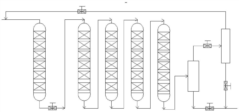
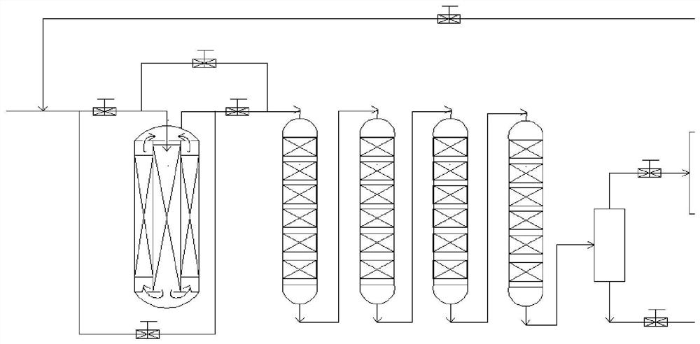
[0044] Adopt the raw material identical with following comparative example 1, catalyst kind and filling method thereof, carry out such as figure 2 The shown material flow direction of the present invention alternately changes residue hydrogenation fixed-bed reactor, system and technology thereof and such as figure 1 The process operation comparison of the conventional residual oil hydrogenation fixed-bed reactor, system and its process is shown.

[0045] Wherein, the reactor of the present invention that material flow changes alternately is used as protective agent and / or demetallization reactor, i.e. the first reactor, such as figure 2 As shown, the catalyst bed in the reactor is physically divided into two sandwich structures with equal cross-sectional areas by a cylinder with the same central axis as the reactor cylinder, and its height is the original conventional reactor ( figure 11 / 2 of the height of the first reactor in the cylinder), the flow direction of the residu...

Embodiment 2

[0058] Using the same raw materials, functional catalysts, catalyst gradation loading ratios and reaction conditions as in the following comparative example 2, carry out as follows figure 2 The shown residue hydrogenation fixed-bed reactor of the present invention, system and technology thereof and such as figure 1 The process operation comparison of the conventional residual oil hydrogenation fixed-bed reactor, system and its process is shown.

[0059] Wherein, the reactor in which the material flow direction of the present invention is alternately changed is used as a protective agent and / or a demetallization reactor, that is, the first reactor, and the catalyst bed in the reactor is covered by one having the same central axis as the reactor cylinder The cylinder is physically divided into two sandwich structures with equal cross-sectional areas, and its height is the original conventional reactor ( figure 1 1 / 3 of the height of the first reactor in the cylinder), the flo...


PUM

PropertyMeasurementUnit
densityaaaaaaaaaa

Abstract

The invention discloses a residual oil hydrogenation reactor with alternately changed material flow directions, a residual oil hydrogenation system containing the reactor and a residual oil hydrogenation process. The internal space of the reactor is provided with a cylindrical interlayer with the same central axis as the reactor cylinder; according to the reactor, under a condition that the volumeof an original reactor and the catalyst filling amount are not changed, the cylinder is divided into two interlayers with equal sectional areas; the height of the reactor is 1 / N of that of the original reactor, wherein N is more than or equal to 2, the flow directions of residual oil materials in two adjacent catalyst bed layers which are physically separated by the cylinder and have the same sectional area are just opposite; when the pressure drop of the catalyst bed layers is greater than 0.3 time of the maximum pressure drop design value, through a preset switch and / or a valve of an external pipeline, the flow direction of the residual oil raw material and a hydrogenation product in the reactor is changed, and the reverse alternate change of the flow direction of the residual oil raw material in the reactor is realized; the reactor can increase the contact sectional area of the fresh residual oil raw material and the catalyst by changing the flowing direction of the raw material todisperse the impurity deposition position and reducing the height of the reactor when N is more than or equal to 3, and thus the pressure drop of the whole catalyst bed layers of the reactor is relieved and the service cycle is prolonged.

Description

technical field [0001] The invention relates to the technical field of residual oil hydrogenation, and more specifically, relates to a residual oil hydrogenation reactor with alternating material flow direction, a residual oil hydrogenation system containing the reactor and a residual oil hydrogenation process. Background technique [0002] Residual oil (atmospheric residual oil, vacuum residual oil) is the heaviest part remaining after primary processing (atmospheric and vacuum distillation) of crude oil. Compared with light distillate oil, residual oil has complex composition, large average relative molecular mass, high viscosity, high density, low hydrogen-carbon ratio, high carbon residue value, and contains a large amount of metals, sulfur, nitrogen, colloids, asphaltenes, etc. Harmful elements and undesirable components. [0003] Hydrogenation of residual oil is one of the main technical approaches to lighten heavy oil. At present, hydrogenation reaction technologies...

Claims


Application Information

Patent Timeline
Patent Type & Authority Applications(China)
IPC IPC(8): C10G45/02
CPCC10G45/02C10G2300/205C10G2300/202
Inventor 张留明张红勤张俊王红令宋现玺
Owner 中耐工程科技有限公司
Learn More