Boiler feed water system with turbine exhaust steam recovery

A boiler feed water and steam turbine technology, applied in feed water heaters, preheating, steam generation, etc., can solve the problems of low efficiency of thermal power plants, limited energy saving of steam turbine exhaust multi-stage heat recovery technology, and inability to pump exhaust steam from steam turbines into boilers, etc. question

Pending Publication Date: 2020-09-22
管理
View PDF0 Cites 0 Cited by
  • Summary
  • Abstract
  • Description
  • Claims
  • Application Information

AI Technical Summary

Problems solved by technology

[0002] At present, the well-known thermal power is limited by the destructive power of the "cavitation" impact of the high-potential energy feed water of the steam boiler that cannot be borne by the conventional boiler feed water pump. However, it has to develop towards ultra-supercritical and extreme-efficiency cooling towers. The entire thermal power plant has never been able to directly pump even part of the exhaust steam from the steam turbine into the boiler. In addition, the multi-stage heat recovery technology of steam turbine exhaust is also very limited in energy saving. As a result, all thermal power and nuclear power related to steam turbine power generation or power conversion in the world are all stagnant at the level of "35-50%" (the root cause is concentrated in "excessive loss of refrigerant", the problem is in the feed water pump The higher the flow pressure head, the steam-water mixture will inevitably produce thousands or even thousands of liquid vapor cavity water impacts per second in the pump body, and this impact force will inevitably produce destructive power to any material) The efficiency of all thermal power plants in the world has been kept below 45%. Even the combination of gas turbines combined with ultra-supercritical boilers for combined cycle power generation is rare with a super-efficiency of about 50% (Western scholars such as the United States and Japan) It is predicted that "62% plant efficiency" will be ten years later, and it will be about 65-70% in twenty years)

Method used


Image

  • Boiler feed water system with turbine exhaust steam recovery
  • Boiler feed water system with turbine exhaust steam recovery
  • Boiler feed water system with turbine exhaust steam recovery

Examples


Embodiment Construction

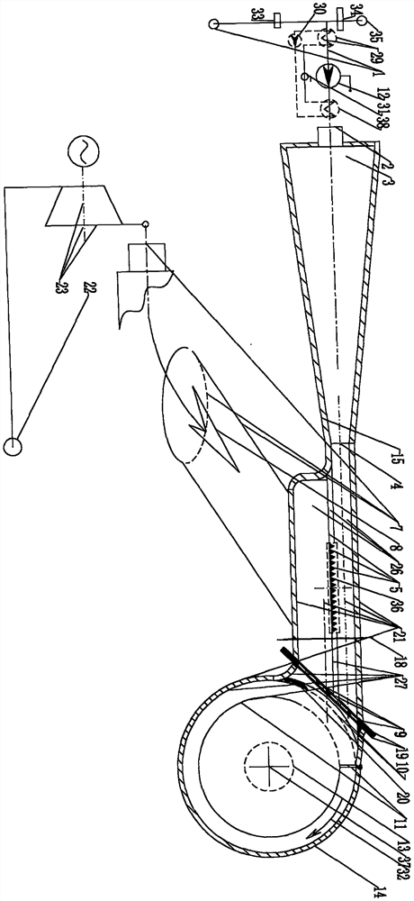
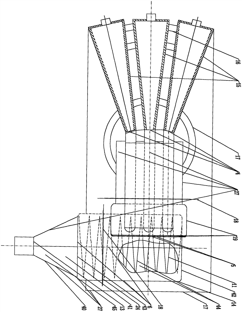
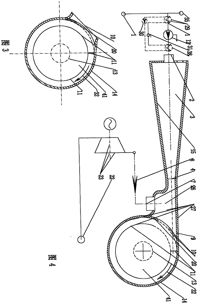
[0011] exist figure 1 Among them, the steam-water mixing feedwater assembly 27 flows through the small split pipe 1 through the economizer 33, the evaporative cooler 29, and the feedwater pump 12 (cooled by the evaporative cooler 29, and the water is used as the working medium of the Rankine cycle " The heat that exceeds the "safe working temperature" of the pump 12 is first transferred to the condensation heater 32 in the flow-through section of the pump 12 through the compressor 30 before being allowed to enter the pump 12. The flow water enters the injector inlet 2) of several injectors 15 connected in parallel, the injection overpressure chamber 3, the jet outlet 4, the jet water guide strip steam chamber 26 (the horizontal arrangement of several triangular strips 36 combined along the flow) Gripper 5, flat grate 5 is lapped on the oblique grate 9 clamped by the double flange connection assembly 19), the injection volume is wrapped around the steam port 10, and the swirl t...


PUM


Abstract

The invention relates to a boiler feed water system with turbine exhaust steam recovery, in particular to a super energy saving boiler feed water system. 1/10-1/4 of the total exhaust flow of steam turbine in a thermal power plant is condensed, and then jetted by the an ultra-high pressure feed water pump, while the remaining 3/4-9/10 of the exhaust flow of steam are not condensed, and then steamis discharged to the swirl tube. After internal steam and water are fully mixed, normal boiler feed water pressure is reduced to realize the mixed feed water of the steam and water. The system is arranged with a jet device behind a water pump, a steam cavity of a water jet leading belt and a steam water forming cavity, and can used for elimination of quasi total effect regenerative power generation of thermal power plant.

Description

technical field [0001] The invention relates to a boiler feed water system for quasi-full-efficiency reheating of exhaust steam from a steam turbine, in particular, 1 / 10 to 1 / 4 of the total fraction of exhaust steam from a steam turbine is condensed and the remaining 9 / 10 to 3 / 4 of the non-condensed exhaust steam flows into the swirl cylinder after the steam and water are fully mixed and then reduced to the normal boiler feed water pressure to realize the steam and water mixing. Thermal power plants and other super energy-saving boiler feed water systems that eliminate quasi-full-efficiency regenerative power generation (or steam-water mixed flow cold and heat shock). Background technique [0002] At present, the well-known thermal power is limited by the destructive power of the "cavitation" impact of the high-potential energy feed water of the steam boiler that cannot be borne by the conventional boiler feed water pump. However, it has to develop towards ultra-supercritic...

Claims


Application Information

Patent Timeline
Patent Type & Authority Applications(China)
IPC IPC(8): F22D1/28F22D1/32
CPCF22D1/28F22D1/325
Inventor 管理
Owner 管理
Why Eureka
Try Eureka