Device and process for spin-coating polymeric membrane on surface of optical fiber grid region and application

A technology of spin coating and polymer film, which is applied in the direction of cladding optical fiber, grating fiber, measuring device, etc., can solve the problems of harsh polymerization conditions and equipment requirements, difficulty in controlling the thickness of polymer film, and difficulty in obtaining performance sensors, etc., to achieve The effect of high coating process efficiency, excellent gas selectivity, and good mechanical properties

Active Publication Date: 2020-09-22
SHANDONG UNIV
View PDF5 Cites 0 Cited by
  • Summary
  • Abstract
  • Description
  • Claims
  • Application Information

AI Technical Summary

Problems solved by technology

However, the inventors found that it is difficult to control the thickness of the polymer film formed by in-situ polymerization, and the polymerization conditions and equipment requirements are harsh, and it is difficult to obtain a sensor with excellent performance.

Method used


Image

  • Device and process for spin-coating polymeric membrane on surface of optical fiber grid region and application
  • Device and process for spin-coating polymeric membrane on surface of optical fiber grid region and application
  • Device and process for spin-coating polymeric membrane on surface of optical fiber grid region and application

Examples


Embodiment 1

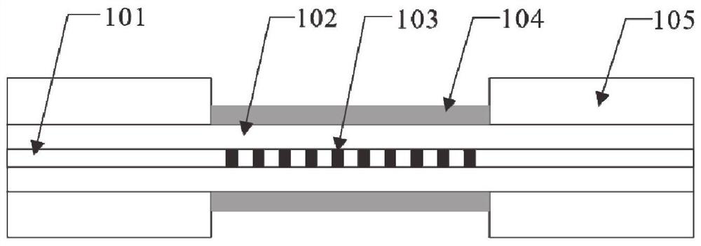
[0058] In this embodiment, taking the coating of polyimide film on the surface of the optical fiber grating region as an example, the spin coating process is described.

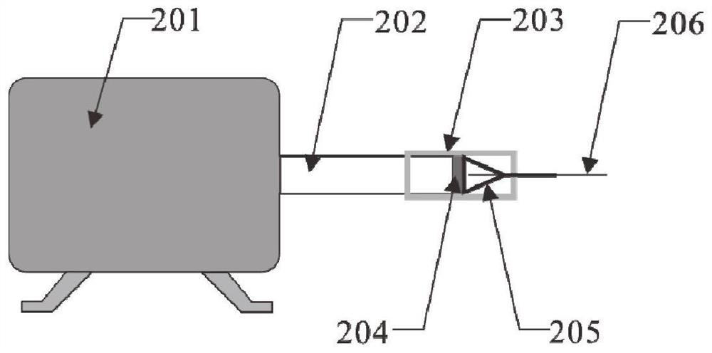
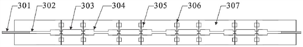
[0059] In this embodiment, the model of the low-speed motor (201) is 220V / 60KTYZ, the rotation speed is 5r / min, and the diameter of the rotating shaft is 7mm. First, the optical fiber (206) is fixed on the mold and connected with the low-speed motor (201) in a logical order on the platform support, wherein the selected optical fiber (206) is an optical fiber with four gate areas, so the selected mold is also Four grid area mould, mold length and solution tank (303) pitch are determined by fiber grating, and mold three-dimensional dimension is selected as 525mm * 25mm * 15mm, and the diameter of the optical fiber limiting groove (302) on the central axis of mold upper surface is 0.5mm, The solution tank (303) specification is 20mm * 5mm * 2.5mm, the size of the longitudinal anti-overflow tank (304) positioned ...

Embodiment 2

[0061] In this embodiment, taking the coating of polyethersulfone film on the surface of the optical fiber grating region as an example, the process of its spin coating is described.

[0062] In this embodiment, the model of the low-speed motor (201) is 220V / 60KTYZ, the rotation speed is 10r / min, and the diameter of the rotating shaft is 7mm. First, on the platform support, the optical fiber (206) is fixed on the mold and connected with the low-speed motor (201) in a logical order, wherein the selected optical fiber (206) is an optical fiber with six gate areas, so the selected mold is also The mold with six grid areas, the length of the mold and the distance between the solution grooves (303) are determined by the fiber grating, the three-dimensional size of the mold is selected as 540mm × 25mm × 15mm, and the diameter of the optical fiber limiting groove (302) on the central axis of the upper surface of the mold is 0.5mm. The solution tank (303) specification is 20mm * 5mm *...

Embodiment 3

[0064] In this embodiment, the coating of polyimide films with different thicknesses on the multi-gate optical fiber is taken as an example, and the spin coating process thereof is described.

[0065] In this embodiment, the model of the low-speed motor (201) is 220V / 60KTYZ, the rotation speed is 5r / min, and the diameter of the rotating shaft is 7mm. First, the optical fiber (206) is fixed on the mold and connected with the low-speed motor (201) in a logical order on the platform support, wherein the selected optical fiber (206) is an optical fiber with four gate areas, so the selected mold is also The four-gate area mold, the length of the mold and the distance between the solution tanks (303) are determined by the fiber grating, the three-dimensional size of the mold is selected as 525mm × 25mm × 15mm, and the diameter of the optical fiber limiting groove (302) on the central axis of the upper surface of the mold is 0.5mm , the solution tank (303) specification is 20mm * 5mm...


PUM

PropertyMeasurementUnit
diameteraaaaaaaaaa
diameteraaaaaaaaaa
lengthaaaaaaaaaa

Abstract

The invention relates to a device and process for spin-coating a polymeric membrane on the surface of an optical fiber grating region and application, and belongs to the technical field of surface treatment of optical fiber gratings, micro-nano machining forming and preparation of optical fiber sensing elements. The device comprises a driving device, a connecting device, a mold, a drying device and a platform support, wherein the driving device, the connecting device and the mold are sequentially arranged on the platform support, part of the mold fixed on the platform support extends into thedrying device, the driving device is connected with an optical fiber through the connecting device, the optical fiber is arranged on the mold, and the driving device drives the optical fiber to rotate. The surface of the optical fiber grating region is coated with the gas-sensitive polymeric membrane which is uniform in thickness distribution and good in mechanical property, and the thickness of the gas-sensitive polymeric membrane can be controlled according to coating conditions, so that the an optical fiber grating gas sensor with excellent gas selectivity, high detection accuracy and highsensitivity is prepared.

Description

technical field [0001] The invention relates to a device, process and application for rotating coating of a polymer film on the surface of an optical fiber grating area, and belongs to the technical fields of optical fiber grating surface treatment, micro-nano processing and molding, and optical fiber sensing element preparation. Background technique [0002] The information disclosed in this background section is only intended to increase the understanding of the general background of the present invention, and is not necessarily taken as an acknowledgment or any form of suggestion that the information constitutes the prior art already known to those skilled in the art. [0003] Fiber Bragg Grating is one of the most rapidly developed and widely used fiber passive devices in recent years. Due to many unique advantages, such as excellent anti-electromagnetic interference ability, high sensitivity, and strong corrosion resistance, fiber gratings have been maturely applied in ...

Claims


Application Information

Patent Timeline
Patent Type & Authority Applications(China)
IPC IPC(8): G02B6/02G01N21/77
CPCG01N21/7703G01N2021/775G02B6/02057
Inventor 徐永正石静玉贾玉玺周振泽高玉山王海庆刘利彬乔从德
Owner SHANDONG UNIV
Why Eureka
Try Eureka