Perovskite battery model based on TiO2 nanocone array

A technology of perovskite cells and nanocones, which can be used in circuits, photovoltaic power generation, electrical components, etc., can solve the problems of less reported performance of PSCs.

Pending Publication Date: 2020-09-22
SHANXI UNIV
View PDF13 Cites 2 Cited by
  • Summary
  • Abstract
  • Description
  • Claims
  • Application Information

AI Technical Summary

Problems solved by technology

However, the performance of PSCs based o

Method used


Image

  • Perovskite battery model based on TiO2 nanocone array
  • Perovskite battery model based on TiO2 nanocone array
  • Perovskite battery model based on TiO2 nanocone array

Examples


Example Embodiment

[0021] In order to have a clearer understanding of the technical features, objectives and effects of the present invention, the specific embodiments of the present invention will now be described in detail with reference to the accompanying drawings.

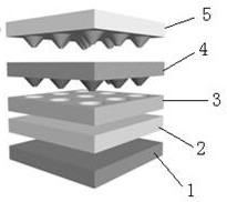
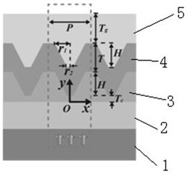
[0022] Such as figure 1 As shown, the present invention provides a TiO-based 2 The perovskite battery model of the nanocone array includes: glass substrate 1, fluorinated tin oxide layer 2, sub-wavelength TiO 2 Nano cone layer 3, MAPbI 3 The photosensitive layer 4 and the Au electrode layer 5;

[0023] Among them, the fluorinated tin oxide layer 2 is coated on the glass substrate 1, and the subwavelength TiO 2 Nano cone layer 3 is made of TiO 2 The layer is set on the fluorinated tin oxide layer 2, TiO 2 Upwardly recessed to form multiple nano-cone barrel structures; fluorinated tin oxide layer 2 and sub-wavelength TiO 2 The nanocone layer 3 together constitutes the battery electron transport layer of the perovskite battery model; MAPb...


PUM


Abstract

The invention relates to a perovskite battery model based on a TiO2 nanocone array. The perovskite battery model comprises a glass substrate, a tin oxide fluoride layer, a sub-wavelength TiO2 nanoconelayer, an MAPbI3 photosensitive layer and an Au electrode layer which are sequentially stacked from bottom to top. Through the novel cell structure design, light absorption of the solar cell is improved, the sensitive characteristic of the cell to the incident light angle is improved, charge extraction is improved, and the solar cell can be used as an ultrathin, semitransparent and flexible device.

Description

technical field [0001] The present invention relates to the field of novel battery technology, more specifically, relates to a TiO-based 2 A perovskite cell model of nanocone arrays. Background technique [0002] One of the current development directions of thin-film perovskite cells is to prepare flexible, wearable, translucent, stacked devices. At the same time, the reduction in the thickness of the active layer can also save the amount of perovskite materials used, reduce the amount of lead (Pb), and reduce the possible pollution risk to the environment. Therefore, ultrathin perovskite solar cells have received great attention. However, the ultra-thin perovskite layer also faces the problem of reducing the absorption of incident light, and it is necessary to increase the light absorption rate of the ultra-thin perovskite active layer. Introducing a two-dimensional patterned structure into thin-film perovskite solar cells (Perovskite Solar Cells, PSCs) to achieve high-e...

Claims


Application Information

Patent Timeline
IPC IPC(8): H01L51/42H01L51/44
CPCH10K30/151H10K30/87H10K30/81Y02E10/549
Inventor 陈名薛太林
Owner SHANXI UNIV
Why Eureka
Try Eureka