Cabin temperature detector and manufacturing method thereof

A technology of a temperature detector and a manufacturing method, which is applied to the temperature measurement of moving fluids, thermometers, and parts of thermometers, etc., can solve the problems of insufficient optimization of the production process, low product quality, and low production efficiency of the cabin temperature detector, and achieve Improve quality and production efficiency, improve assembly efficiency, and have good sealing effects

Pending Publication Date: 2020-09-25
XINXIANG GUANGMING ELECTRIC APPLIANCE CO LTD
View PDF0 Cites 0 Cited by
  • Summary
  • Abstract
  • Description
  • Claims
  • Application Information

AI Technical Summary

Problems solved by technology

[0005] The present invention aims to provide a cabin temperature detector to solve the technical problems of low production efficiency and low product quality caused by insufficient optimization of the production process of the cabin temperature detector in the prior art

Method used


Image

  • Cabin temperature detector and manufacturing method thereof
  • Cabin temperature detector and manufacturing method thereof
  • Cabin temperature detector and manufacturing method thereof

Examples


Embodiment 1

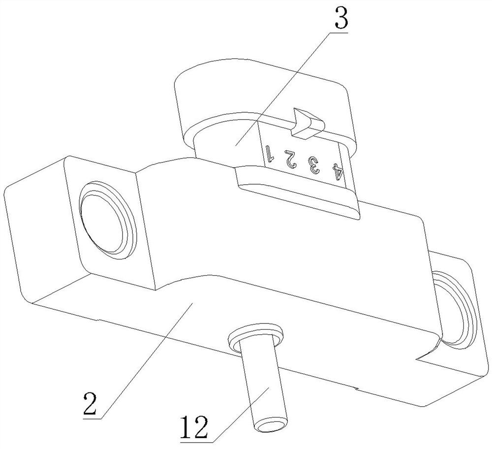
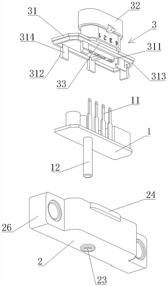
[0044] A cabin temperature detector, see Figure 1 to Figure 3 .

[0045] The engine room temperature detector provided by the embodiment of the present invention includes a circuit board 1, which is a double-sided circuit board, electronic components can be arranged on both sides of the upper and lower sides, and a temperature detection circuit is arranged on the circuit board 1, and the temperature detection circuit is electrically connected There are four connecting terminals 11 arranged on the upper surface of the circuit board 1, and these four connecting terminals are input signal lines, output signal lines, control unit ground lines and instrument panel ground lines respectively.

[0046] A temperature probe 12 is provided on the lower surface of the circuit board 1. The temperature detection circuit includes a temperature sensing element. The temperature probe 12 is located at one end of the circuit board 1 and contacts the temperature sensing element, so that the temp...

Embodiment 2

[0060] A kind of manufacture method of cabin temperature detector, please refer to Figure 4 .

[0061] The manufacturing method of the cabin temperature detector of this embodiment comprises the following steps:

[0062] Step S100, making a temperature detection circuit board, a lower casing and an upper cover.

[0063] In this step, the circuit board, lower case and upper cover are manufactured according to the principle, structure and shape of the circuit board, lower case and upper cover in Embodiment 1. Dividing the entire engine room temperature detector into these three parts is convenient for later assembly, which is conducive to simplifying the assembly process and improving production efficiency.

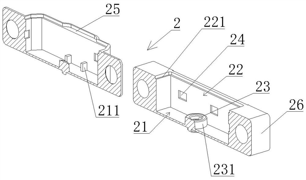
[0064] Step S200, loading the circuit board into the lower casing, and allowing the temperature probe to pass through the perforation.

[0065] In this step, the bottom surface of the circuit board is supported on the support column and two support platforms on the bott...


PUM


Abstract

The invention discloses a cabin temperature detector and a manufacturing method thereof. The cabin temperature detector comprises a circuit board, a lower shell and an upper cover, wherein a temperature detection circuit is arranged on the circuit board, a temperature probe is arranged on the lower surface of the circuit board, the temperature detection circuit comprises a temperature sensing element, one end, located at the circuit board, of the temperature probe makes contact with the temperature sensing element, a cavity for accommodating the circuit board is formed in the upper cover, an opening is formed in the top of the lower shell, the lower end of the temperature probe extends out of the lower shell from a through hole, the lower shell comprises a cover body used for sealing the opening, jacks corresponding to the wiring terminals on the circuit board are formed in the cover body, the circuit board is installed in the lower shell, a packaging glue is injected into the cavity,and the upper cover covers the lower shell. According to the cabin temperature detector, the manufacturing process is optimized, the production efficiency is improved, the product quality can be ensured in the batch manufacturing process, the qualification rate of products is improved, and the cabin temperature detector is long in service life and stable and reliable in the using process.

Description

technical field [0001] The invention relates to the technical field of temperature detection devices, in particular to a cabin temperature detector and a manufacturing method thereof. Background technique [0002] There are temperature sensors in the engine compartments of various locomotives such as cars, engineering vehicles, and military vehicles to detect temperature. These temperature sensors generally include coolant temperature sensors, intake air temperature sensors, transmission oil temperature sensors, exhaust temperature sensors, EGR exhaust gas circulation temperature sensors, and the like. Different temperature sensors have their own functions. For example, the intake air temperature sensor is responsible for detecting and controlling the concentration of the mixed steam. The lower the temperature, the thicker the mixed steam, and the higher the temperature, the thinner the mixed steam; When the machine is running, the engine speed is low, the speed is high whe...

Claims


Application Information

Patent Timeline
Patent Type & Authority Applications(China)
IPC IPC(8): G01K13/02G01K1/12G01K1/14
CPCG01K1/12G01K1/14G01K13/02
Inventor 胡广举寿青松孔令宾刘洋
Owner XINXIANG GUANGMING ELECTRIC APPLIANCE CO LTD
Why Eureka
Try Eureka