
Cleaning device and cleaning method for optical coating clamp

A technology of optical coating and cleaning device, which is applied in the direction of using liquid cleaning methods, chemical instruments and methods, cleaning methods and utensils, etc., which can solve the problems of low efficiency, slow cleaning speed, long time, etc., and achieve improved cleaning efficiency, cleaning High efficiency and short cleaning time

Active Publication Date: 2020-09-29
潍坊华光光电子有限公司
View PDF9 Cites 3 Cited by
  • Summary
  • Abstract
  • Description
  • Claims
  • Application Information

AI Technical Summary

Problems solved by technology

However, due to the precision and delicateness of the coating fixture, it is impossible to attach aluminum foil paper, and sandblasting will cause its deformation and make it unusable
At present, it is generally used to soak the fixture in alkaline solution, but this method takes a long time, has low efficiency and cannot clean some hidden corners thoroughly.
[0004] Chinese patent CN 204237864 U discloses a cleaning device for coating machine clamps. The device includes guide rails, transmission chains, lye tanks, washing tanks, heating devices, drying devices and controllers. The guide rails form a rectangle, and the transmission chains are along the The guide rail is set under the guide rail, the running mode of the transmission chain is counterclockwise, the transmission chain is evenly provided with suspension rings, and a hook is provided under each suspension ring, and two downward protrusions on the guide rail are respectively provided with There are lye tank and water washing tank. The lye tank is provided with a heating device, which can clean the coating fixtures in batches, but the cleaning effect of the cleaning device provided by the invention is not thorough, and the lye immersion alone cannot effectively make the clamps The membrane material falls off completely
However, the invention is soaked in cleaning solution, resulting in slow cleaning speed and incomplete cleaning.

Method used


Image

  • Cleaning device and cleaning method for optical coating clamp
  • Cleaning device and cleaning method for optical coating clamp
  • Cleaning device and cleaning method for optical coating clamp

Examples


Embodiment 1

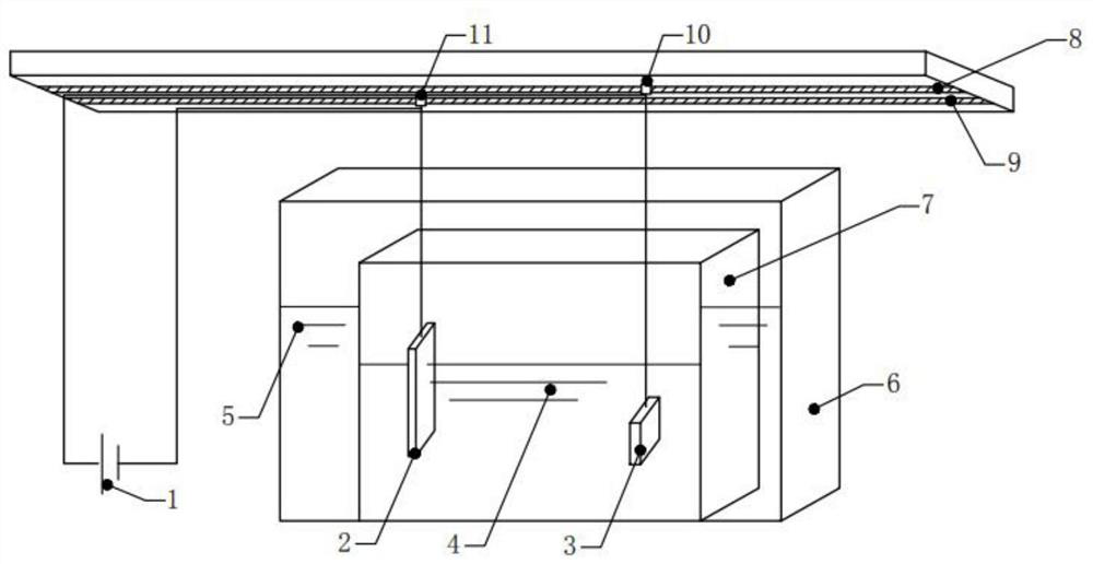
[0039] A cleaning device for an optical coating jig, such as figure 1As shown, it includes a DC power supply 1, an ultrasonic oscillator 6 and a reaction vessel 7; the model of the DC power supply 1 is AN5330-150, one end of the positive lead is connected to the positive pole of the DC power supply 1, and the other end of the positive lead is connected to the optical coating fixture 3 One end of the negative lead is connected to the negative pole of the DC power supply 1, and the other end of the negative lead is connected to the platinum sheet 2; the optical coating jig 3 as the anode and the platinum sheet 2 as the cathode are placed in the electrolyte 4 In the reaction vessel 7, in this embodiment, the reaction vessel 7 is a polytetrafluoroethylene container, the platinum sheet 2 is partially immersed in the electrolyte 4, and the optical coating jig 3 is completely immersed in the electrolyte 4; In the ultrasonic oscillator 6 of the ionized water 5. Among them, NaOH, NaCl...

Embodiment 2

[0054] According to the method for optical coating fixture cleaning described in embodiment 1, its difference is:

[0055] The optical coating jig 3 used in this embodiment has the same state as the optical coating jig 3 used in Embodiment 1.

[0056] NaOH, NaCl and H in electrolyte 4 2 O mass ratio 2:5:4.

[0057] In step (1), the optical coating jig 3 is put into the electrolyte solution 4 for immersion treatment, and the immersion time is 30 minutes.

[0058] In step (2), the DC power supply 1 is started first, and the DC power supply 1 adopts a constant voltage mode. The working time of the DC power supply 1 is 20 minutes, and the DC voltage is 30V.

[0059] In step (3), keep the DC power supply 1 to continue working, and at the same time turn on the ultrasonic oscillator 6, and start the ultrasonic oscillator 6 to work for 20 minutes.

[0060] In step (4), the optical coating jig 3 is taken out, and the optical coating jig 3 is rinsed with deionized water for 20 minute...


PUM


Abstract

The invention relates to a cleaning device and a cleaning method for an optical coating clamp. The cleaning device for the optical coating clamp comprises a direct-current power supply, an ultrasonicoscillator and a reaction container. The cleaning method of the cleaning device for the optical coating clamp comprises the following steps that (1), the direct-current power supply is started, and the optical coating clamp is subjected to electrochemical corrosion; (2), the ultrasonic oscillator and the direct-current power supply simultaneously work to clean the optical coating clamp; (3), the optical coating clamp is washed; (4), the optical coating clamp is blown for drying; and (5), the optical coating clamp is dried. According to the cleaning device and method for the optical coating clamp, the optical coating clamp is pretreated firstly, then a surface film layer of the optical coating clamp is treated through the method of combining electrochemical corrosion and ultrasonic oscillation, and compared with a traditional chemical soaking method and a traditional ultrasonic cleaning method, the cleaning time is short, and the cleaning efficiency is high.

Description

technical field [0001] The invention relates to a cleaning device and a cleaning method for an optical coating fixture, belonging to the field of vacuum coating cleaning on the cavity surface of a semiconductor laser. Background technique [0002] Semiconductor lasers are widely used in various fields due to their unique advantages. Semiconductor lasers have been pursuing the characteristics of high power, high conversion efficiency, and long life. Therefore, semiconductor lasers need to be coated on the cavity surface to optimize their reflectivity. Vacuum coating on the cavity surface of semiconductor lasers refers to the process of coating several layers (or dozens of layers) of dielectric films on the cavity surface after cleavage. The purpose of vacuum coating is to increase or reduce the reflectivity of the cavity surface of semiconductor lasers and protect The cavity surface is not polluted by the external environment. The process of vacuum coating process is a proc...

Claims


Application Information

Patent Timeline
Patent Type & Authority Applications(China)
IPC IPC(8): B08B3/08B08B3/10B08B3/12B08B3/02F26B5/04
CPCB08B3/08B08B3/10B08B3/12B08B3/02F26B5/04
Inventor 孙春明苏建殷方军陈康任夫洋郑兆河
Owner 潍坊华光光电子有限公司
Learn More