Eureka AIR delivers breakthrough ideas for toughest innovation challenges, trusted by R&D personnel around the world.

Boat bottom cleaning robot

A technology for cleaning robots and ship bottoms, which is applied to ship cleaning devices, hulls, motor vehicles, etc. It can solve the problems of low cleaning efficiency, increased hull resistance, and long cleaning time, achieving low cleaning costs, comprehensive cleaning, and simple structure Effect

Pending Publication Date: 2020-09-29
未来海工智能装备(山东)有限公司
View PDF1 Cites 3 Cited by
  • Summary
  • Abstract
  • Description
  • Claims
  • Application Information

AI Technical Summary

Problems solved by technology

[0002] The crawler-type cavitation jet ship bottom cleaning robot is used to remove the attached organisms attached to the bottom and side of the ship underwater. These organisms are attached to the hull and have a strong reproductive ability. The resistance of the hull during driving, and the acid corrosion products produced by these organisms are severely corrosive to the hull, and its corrosion degree is even far stronger than that of seawater. Therefore, regular cleaning is an essential part of hull maintenance. Now the bottom of the ship is commonly used. There are two schemes, one is cleaning in the dock, this scheme needs to drive the hull into the dock, the number of docks is limited, and the cost of use is very high, especially for large docks, which are generally only used for large-scale inspection and maintenance of the hull , and it takes a long time to clean the dock, which increases the loss of the ship's suspension
The other is manual cleaning by divers. This method is inefficient and has high requirements for divers.

Method used


Image

  • Boat bottom cleaning robot
  • Boat bottom cleaning robot
  • Boat bottom cleaning robot

Examples


Embodiment Construction

[0023]The specific implementation manners of the present invention will be further described in detail below in conjunction with the accompanying drawings.

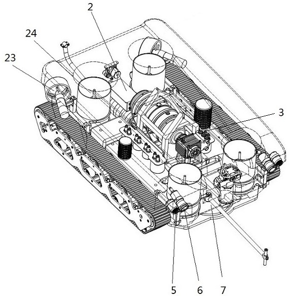
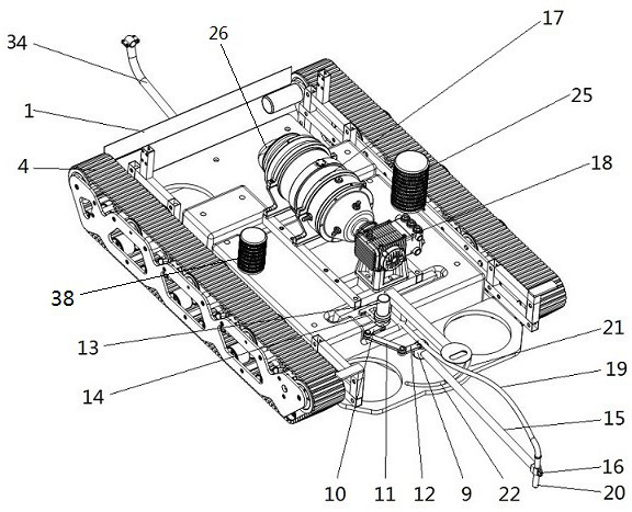
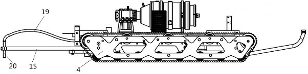
[0024] A ship bottom cleaning robot, comprising a frame 1, the frame 1 is provided with an electrical cabin 2, a traveling mechanism 4 and an image scanning device 5, the electrical cabin 2 is provided with a control system, and the control system communicates with the The water control box is connected, and it is characterized in that: the frame 1 is provided with a cleaning driving mechanism 3 and a nozzle driving mechanism 7, and the cleaning driving mechanism 3 includes a driving assembly, a water inlet pipe, a water outlet pipe 19 and a cavitation nozzle 20, Described driving assembly comprises plunger pump 18 and the underwater motor 17 of driving plunger pump 18, described underwater motor 17 and plunger pump 18 are respectively fixed on the frame 1, and described underwater motor 17 is connected with control system...


PUM


Abstract

The invention relates to the field of underwater mechanical equipment, in particular to a boat bottom cleaning robot. The boat bottom cleaning robot comprises a rack; an electrical cabin, a walking mechanism and image scanning equipment are arranged on the rack; a control system is arranged in the electrical cabin; a cleaning driving mechanism and a spray head driving mechanism are arranged on therack; the cleaning driving mechanism comprises a water inlet pipe, a water outlet pipe, a cavitation nozzle, a plunger pump and an underwater motor; an oil pressure balancing device is arranged on the underwater motor; the oil pressure balancing device can be composed of hydraulic oil and a pressure regulating cavity, and can also be composed of an oil bag, hydraulic oil and an oil pipe. The spray head driving mechanism comprises an output shaft, a rotating shaft, a first connecting plate, a second connecting plate, a third connecting plate, a driving motor, a bracket, a supporting rod and aspray head clamp. The cavitation nozzle is fixedly clamped in the spray head clamp, and the cavitation nozzle is driven by the spray head driving mechanism. The internal pressure and the external pressure of the motor can be automatically adjusted underwater, the operation is convenient, the cleaning is comprehensive, the cleaning cost is low, the gravity center is low, and the safety is good.

Description

technical field [0001] The invention relates to the field of underwater mechanical equipment, in particular to a ship bottom cleaning robot. Background technique [0002] The crawler-type cavitation jet ship bottom cleaning robot is used to remove the attached organisms attached to the bottom and side of the ship underwater. These organisms are attached to the hull and have a strong reproductive ability. The resistance of the hull during driving, and the acid corrosion products produced by these organisms are severely corrosive to the hull, and its corrosion degree is even far stronger than that of seawater. Therefore, regular cleaning is an essential part of hull maintenance. Now the bottom of the ship is commonly used. There are two schemes, one is cleaning in the dock, this scheme needs to drive the hull into the dock, the number of docks is limited, and the cost of use is very high, especially for large docks, which are generally only used for large-scale inspection and ...

Claims


Application Information

Patent Timeline
Patent Type & Authority Applications(China)
IPC IPC(8): B63B59/10B62D55/075
CPCB62D55/075B63B59/10
Inventor 陶泽文陶一锐杜阳张梦涛王亚丽孙华磊
Owner 未来海工智能装备(山东)有限公司
Why Eureka
Eureka Blog
Learn More