Filamentous arc plasma exciter based on swirl holes

An arc plasma and plasma technology, applied in the direction of plasma, electrical components, machines/engines, etc., can solve the problems of low combustion efficiency and inability to discharge, and achieve the effect of improving combustion efficiency, obvious effect and simple structure

Active Publication Date: 2020-10-02
AIR FORCE UNIV PLA
View PDF8 Cites 8 Cited by
  • Summary
  • Abstract
  • Description
  • Claims
  • Application Information

AI Technical Summary

Problems solved by technology

[0004] In order to overcome the deficiencies in the prior art that the sliding arc plasma cannot discharge when the inlet air flow rate is 0, the combustion efficiency is low, and there is no need to set up a special gas supply system and oil supply system, the present invention proposes a swirl-based Hole Filament Arc Plasma Actuator

Method used


Image

  • Filamentous arc plasma exciter based on swirl holes
  • Filamentous arc plasma exciter based on swirl holes
  • Filamentous arc plasma exciter based on swirl holes

Examples


Embodiment 1

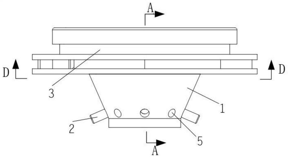
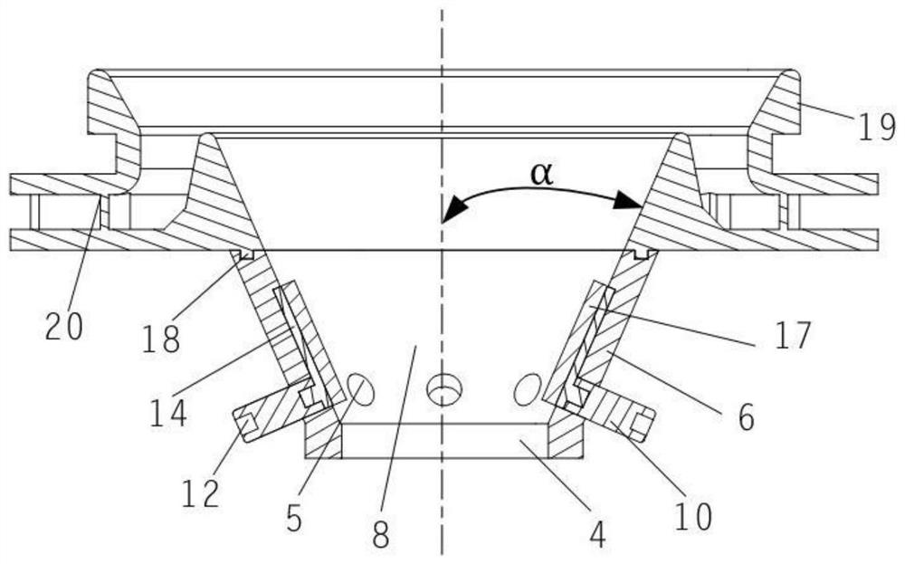
[0043] This embodiment is a filamentary arc plasma exciter based on swirl holes, which includes an inner plasma cyclone 1, an electrode 2 for generating an arc, and an outer cyclone 3 made of ceramics. The inner plasma cyclone 1 and the outer cyclone 3 adopt a split structure.

[0044] The number of the electrodes 2 is a; a=2-5. The electrodes are evenly distributed on the shell, and the electrodes are respectively installed in the swirl holes evenly distributed on the shell. Each electrode divides the circumference of the shell into n arc segments of equal length, and makes the number of swirl holes distributed on the n arc segments equal. The number of the swirl holes 5 is a multiple of m from 6 to 15; m=2,3,4,....

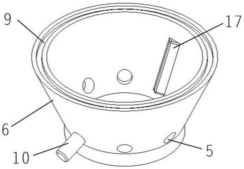
[0045] A plurality of swirl holes 5 are evenly distributed on the casing 6; the vertical distance between the center of each swirl hole and the lower end surface of the casing is 2 mm to 4 mm. The diameter of the swirl hole is 1 mm to 4 mm, and is the same diamete...

Embodiment 2

[0060] This embodiment is a filamentary arc plasma exciter based on swirl holes, which includes an inner plasma cyclone 1, an electrode 2 for generating an arc, and an outer cyclone 3 made of ceramics. The inner plasma cyclone 1 and the outer cyclone 3 adopt a split structure. The number of the electrodes 2 is a; a=2-5. The electrodes are evenly distributed on the shell, and the electrodes are respectively installed in the swirl holes evenly distributed on the shell. Each electrode divides the circumference of the shell into n arc segments of equal length, and equalizes the number of swirl holes distributed on the n arc segments. The number of the swirl holes 5 is a multiple of m selected from 6-15; m=2,3,4....

[0061] A plurality of swirl holes 5 are evenly distributed on the casing 6; the vertical distance between the center of each swirl hole and the lower end surface of the casing is 2 mm to 4 mm. The diameter of the swirl hole is 1 mm to 4 mm, and is the same diameter as...

Embodiment 3

[0075] This embodiment is a filamentary arc plasma exciter based on swirl holes, which includes an inner plasma cyclone 1, an electrode 2 for generating an arc, and an outer cyclone 3 made of ceramics. The inner plasma cyclone 1 and the outer cyclone 3 adopt a split structure.

[0076] The number of the electrodes 2 is a; a=2-5. The electrodes are evenly distributed on the shell, and the electrodes are respectively installed in the swirl holes evenly distributed on the shell. Each electrode divides the circumference of the shell into n arc segments of equal length, and equalizes the number of swirl holes distributed on the n arc segments. The number of the swirl holes 5 is a multiple of m from 6 to 15; m=2,3,4,....

[0077] A plurality of swirl holes 5 are evenly distributed on the casing 6; the vertical distance between the center of each swirl hole and the lower end surface of the casing is 2 mm to 4 mm. The diameter of the swirl hole is 1 mm to 4 mm, and is the same diameter ...


PUM


Abstract

Provided is a filamentous arc plasma exciter based on swirl holes. An inner layer plasma swirler and an outer layer swirler are of a split type structure. The plurality of swirl holes are evenly distributed in a shell body of the inner layer plasma swirler. Two to five electrodes are disposed in the swirl holes through electrode installing bases correspondingly and divide the circumference of theshell body of the inner layer plasma swirler into n equal-length arc sections. The outer layer swirler is disposed on the upper end face of the inner layer plasma swirler. The filamentous arc discharge as one type of plasma discharge has huge advantages in the aspect of ignition and combustion supporting of a combustion chamber of an aero-engine, and the plasma exciter is combined with the head portion of the combustion chamber, so that ignition and combustion supporting can be integrated, and meanwhile active particles generated by plasma discharge are easily mixed with fuel oil molecules. The filamentous arc plasma exciter overcomes the defect that sliding arc plasmas cannot realize discharging when an inlet air flow rate is 0, improves combustion efficiency, is simple in structure and does not need to be equipped with a special air supply system or a special oil supply system.

Description

Technical field [0001] The invention relates to the technical field of aerodynamic plasma ignition and combustion strengthening, in particular to a filament arc plasma exciter based on swirl holes. Background technique [0002] At present, most of the aviation turbine engines used on aircraft use electric sparks for ignition. The disadvantages of this ignition method are: the ignition energy is small and the ignition conditions are harsh, which affects the improvement of the aero engine performance. [0003] In recent years, plasma ignition combustion-supporting technology has received widespread attention at home and abroad. After extensive research by domestic and foreign experts and scholars, plasma has shown great advantages in the ignition and combustion-supporting aspects of aero-engine combustion chambers. Plasma ignition can just solve the shortcomings of spark plug ignition. It has been proved that the advantages of plasma ignition to assist combustion include: improving...

Claims


Application Information

Patent Timeline
Patent Type & Authority Applications(China)
IPC IPC(8): F02C7/266H05H1/48
CPCF02C7/266H05H1/48
Inventor 于锦禄张磊陈朝蒋永健蒋陆昀陈一赵兵兵田裕
Owner AIR FORCE UNIV PLA
Why Eureka
Try Eureka