Broadband variable gain amplifier with high linearity

A gain amplifier and high linearity technology, which is applied in the direction of improving the amplifier to expand bandwidth, gain control, and amplification control, and can solve problems such as loop gain drop and feedback resistance increase

Pending Publication Date: 2020-10-02
FUDAN UNIV
View PDF0 Cites 7 Cited by
  • Summary
  • Abstract
  • Description
  • Claims
  • Application Information

AI Technical Summary

Problems solved by technology

The linearity is mainly related to the loop gain. In the case of high gain, the re

Method used


Image

  • Broadband variable gain amplifier with high linearity
  • Broadband variable gain amplifier with high linearity
  • Broadband variable gain amplifier with high linearity

Examples


Embodiment Construction

[0024] Hereinafter, the present invention will be described in more detail with reference to the accompanying drawings. In the various figures, identical elements are indicated with similar reference numerals. For the sake of clarity, various parts in the drawings have not been drawn to scale. Also, some well-known parts may not be shown in the drawings.

[0025] In the following, many specific details of the present invention are described, such as device structures, materials, dimensions, processing techniques and techniques, for a clearer understanding of the present invention. However, the invention may be practiced without these specific details, as will be understood by those skilled in the art.

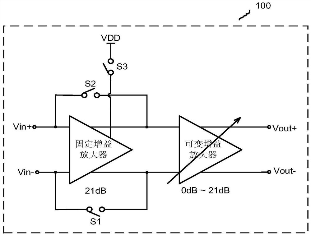
[0026] figure 1 It is a schematic diagram of the overall structure of the variable gain amplifier of the present invention.

[0027] Such as figure 1 As shown, the entire chain includes a fixed-gain amplifier in the first stage and a variable-gain amplifier in the second s...


PUM


Abstract

The invention belongs to the technical field of integrated circuits, and particularly relates to a broadband variable gain amplifier with high linearity. The variable gain amplifier comprises a first-stage fixed gain amplifier, wherein the gain of the first-stage fixed gain amplifier is fixed to be 21 dB; three switches, wherein two switches are connected with the first-stage fixed gain amplifierin parallel, the third switch is connected between the first-stage fixed gain amplifier and the power supply, the two switches which are connected in parallel enable the first-stage fixed gain amplifier to be short-circuited in a low-gain mode and to be disconnected in a high-gain mode, and the third switch is disconnected in the low-gain mode and to be closed in the high-gain mode; and the inputend of the second-stage variable gain amplifier is connected with an input signal of the whole link in a low-gain mode and is connected with the output of the first-stage fixed gain amplifier in a high-gain mode, and the gain change range of the second-stage variable gain amplifier is changed from 0 dB to 21 dB. The gain amplifier can be used for the sampling front end of a high-precision analog-to-digital converter, has variable gain, and realizes high linearity while keeping wide bandwidth.

Description

technical field [0001] The invention belongs to the technical field of integrated circuits, and in particular relates to a variable gain amplifier. Background technique [0002] High-precision, low-power analog-to-digital converters are an important part of wideband receivers, and successive approximation analog-to-digital converters have received widespread attention due to their low power consumption. At present, there are many studies devoted to improving the performance of the core chip of the successive approximation analog-to-digital converter, but there are few studies on the driving circuit of the analog-to-digital converter. For successive approximation analog-to-digital converters, the capacitance of the sampling capacitor is usually relatively large, and it is very difficult to drive a large capacitor in a relatively short sampling window, which makes the driving circuit a high-speed and high-precision analog-to-digital converter. The bottleneck of device researc...

Claims


Application Information

Patent Timeline
IPC IPC(8): H03F1/42H03G3/20
CPCH03F1/42H03G3/20
Inventor 马顺利姚玉婷任俊彦
Owner FUDAN UNIV
Why Eureka
Try Eureka