Garbage treatment device for building construction

A technology for garbage disposal and building construction, which is applied in grain processing, mixers with rotary stirring devices, and manufacturing tools, etc., can solve problems such as physical harm to workers, no dust absorption mechanism, and reduced device practicability.

Inactive Publication Date: 2020-10-09
袁国初
View PDF1 Cites 5 Cited by
  • Summary
  • Abstract
  • Description
  • Claims
  • Application Information

AI Technical Summary

Problems solved by technology

[0004] The above-mentioned patent also has the following disadvantages: when the construction waste is crushed, the waste will produce relatively large dust, but the above-mentioned device is not provided with an absorption mechanism for the dust, and long-term inhalation of dust will be harmful to the health of the staff and also It will cause certain pollution to the environment and reduce the practicability of the device

Method used


Image

  • Garbage treatment device for building construction
  • Garbage treatment device for building construction
  • Garbage treatment device for building construction

Examples


Embodiment 1

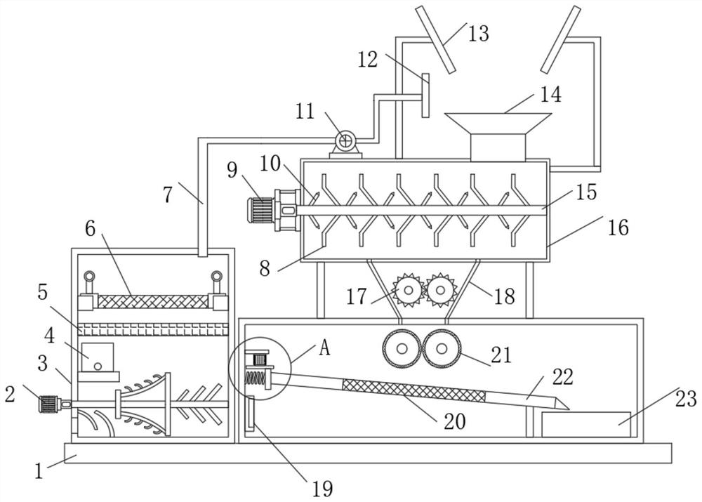
[0030] refer to Figure 1-4 , a kind of garbage treatment device for building construction, comprising a base plate 1, the top outer wall of the base plate 1 is fixed with a filter box 3 and a box body by screws, and the top outer wall of the box body is provided with a crushing tank 18, and the top outer wall of the crushing tank 18 is welded with The first crushing box 16, and the top outer wall of the first crushing box 16 is fixed with fan 11 by screw, the top outer wall of the first crushing box 16 is provided with dust suction pan 12, the input of one side inner wall of dust suction pan 12 and blower fan 11 The end is connected with the same second conduit through the flange, the output end of the fan 11 and the top inner wall of the filter box 3 are connected with the same first conduit 7 through the flange, and the inner wall of the filter box 3 is clamped with a filter screen 6 and activated carbon adsorption Layer 5, the inner wall of the filter box 3 is fixed with a...

Embodiment 2

[0038] refer to Figure 5 , a garbage disposal device for building construction. Compared with Embodiment 1, this embodiment also includes a liquid level sensor 39 fixed on the inner wall of the bottom of the box by screws, and a display screen 40 is fixed on one side of the outer wall of the box by screws, and The signal input end of the display screen 40 is connected to the processor through a signal line, and the signal output end of the liquid level sensor 39 is connected with the signal input end of the processor through a signal line.

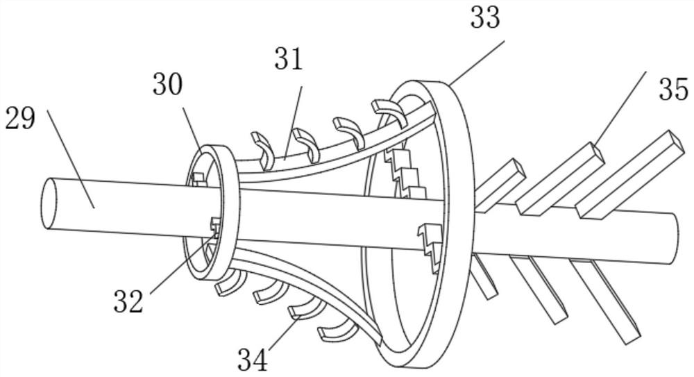
[0039] Connect the equipment to the power supply, import the construction waste from the material guide plate 13 into the first crushing box 16, turn on the second motor 9 and the fan 11, and the fan 11 will import the dust into the filter box 3, and pass through the filter screen 6 and the activated carbon adsorption layer 5 Filter and adsorb the dust, turn on the first motor 2, the first motor 2 drives the first rotating rod 29 to rotat...


PUM


Abstract

The invention belongs to the technical field of buildings, particularly relates to a garbage treatment device for building construction, and provides the following scheme for solving the dust removalproblem. The garbage treatment device comprises a bottom plate, a filter box and a box body are arranged on the outer wall of the top of the bottom plate, a crushing tank is arranged on the outer wallof the top of the box body, and a first crushing box is arranged on the outer wall of the top of the crushing tank; and a draught fan is arranged on the outer wall of the top of the first crushing box, a dust suction disc is arranged on the outer wall of the top of the first crushing box, the inner wall of one side of the dust suction disc and the input end of the draught fan are provided with asame second guide pipe, and the output end of the draught fan and the inner wall of the top of the filter box are provided with a same first guide pipe. According to the garbage treatment device, through arranging the dust suction disc, the draught fan, a filter screen, an activated carbon adsorption layer, an aromatherapy agent, a first motor, a first rotating rod, a first stirring ring, a secondstirring ring, a connecting rod, a first crushing block, a second crushing block and the connecting rod, the draught fan is started, dust is guided into the filter box, and the dust is filtered and adsorbed through the filter screen and the activated carbon adsorption layer.

Description

technical field [0001] The invention relates to the field of building technology, in particular to a garbage disposal device for building construction. Background technique [0002] Construction waste refers to the general designation of muck, waste concrete, waste masonry and other waste produced in the production activities of the construction industry such as demolition, construction, decoration and repair. According to the source of generation, construction waste can be divided into construction waste, decoration waste, demolition waste and construction mud. [0003] After retrieval, the Chinese patent authorization number is CN110252502A, which discloses a kind of garbage crushing device for environmental protection, including a device main body, a hydraulic cylinder, a first filter plate, a storage box, a feeding conveyor belt and a second motor. [0004] The above-mentioned patent also has the following disadvantages: when the construction waste is crushed, the waste...

Claims


Application Information

Patent Timeline
Patent Type & Authority Applications(China)
IPC IPC(8): B09B3/00B09B5/00B02C21/00B02C18/14B02C18/24B02C18/18B02C4/08B02C4/42B30B9/20B08B15/04B01D46/00B01D46/10B01F7/02B01F7/04
CPCB09B3/00B09B5/00B02C21/00B02C18/14B02C18/24B02C18/18B02C4/08B02C4/42B30B9/20B08B15/04B01D46/0036B01D46/10B01D46/62B01F27/11B01F27/60B01F27/70
Inventor 袁国初
Owner 袁国初
Why Eureka
Try Eureka