Improved heat pump vacuum low-temperature evaporation and concentration system

An evaporation concentration system, vacuum and low temperature technology, applied in the direction of heating water/sewage treatment, special treatment targets, chemical instruments and methods, etc., can solve the problems of distilled water temperature rise, temperature rise, high-concentration industrial wastewater outsourced disposal costs, etc. Achieve good water quality and save energy

Active Publication Date: 2020-10-09
VISBE XIAMEN ENVIRONMENT TECH CO LTD
View PDF5 Cites 0 Cited by
  • Summary
  • Abstract
  • Description
  • Claims
  • Application Information

AI Technical Summary

Problems solved by technology

[0002]The outsourced treatment of high-concentration industrial wastewater is expensive, and traditional treatment methods, such as membrane concentration technology, ultra-high frequency vibration concentration technology, disc tube reverse osmosis technology, etc. , because the concentration of the solute is too high and cannot be further concentrated; another example is the three-effect evaporator or MVR concentration equipment, the evaporation temperature is more than 90 to 100 degrees, the speed of scale generation is fast, the maintenance cost is high, and the service life of the equipment is short
[0003]A patent with application number 201810062520.3 discloses a heat pump vacuum low-temperature evaporation and concentration system, which has the following deficiencies: 1. For the heating Carnot cycle system, Most of the mechanical energy input to the heating system compressor to do work is converted into thermal energy input. If effective heat dissipation measures cannot be taken, the

Method used


Image

  • Improved heat pump vacuum low-temperature evaporation and concentration system

Examples


Embodiment Construction

[0027] The present invention will be further described below in conjunction with the accompanying drawings and specific embodiments.

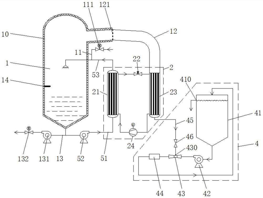
[0028] like figure 1 as shown in figure 1 As shown, an improved heat pump vacuum low-temperature evaporation and concentration system includes an evaporation tank 1, a heating Carnot cycle system 2, and a mixed gas and condensed water removal system 4 containing non-condensable gas. The upper part of the evaporation tank 1 is connected with a waste water inlet pipeline 53 and a steam discharge pipeline 12 , and a liquid level gauge 14 is arranged in the middle of the evaporation tank 1 . The waste water inlet pipeline 53 is provided with a non-evaporated and concentrated waste water replenishment branch 11 , and the non-evaporated and concentrated waste water replenishment branch 11 is provided with a feed valve 111 . A concentrated liquid discharge branch 13 is provided on the pipeline between the bottom of the evaporation tank 1 and the con...


PUM


Abstract

The invention discloses an improved heat pump vacuum low-temperature evaporation and concentration system. The system comprises an evaporation tank, a heating Carnot cycle system and a non-condensablegas-containing mixed gas and condensed water removal system; the upper part of the evaporation tank is connected with a wastewater inflow pipeline and a steam discharge pipeline; a wastewater heatingsystem is arranged between the bottom of the evaporation tank and the wastewater inflow pipeline; a condenser in the heating Carnot cycle system is a heating part in the wastewater heating system; the steam discharge pipeline is connected with the top of an evaporator in the heating Carnot cycle system; the non-condensable gas-containing mixed gas and condensed water removal system comprises a water tank, a water pump, a venturi and a negative-pressure suction pipeline, wherein the water tank, the water pump and the venturi are sequentially connected in a closed-loop mode through pipelines; one end of the negative-pressure suction pipeline is connected with the bottom of the evaporator, and the other end of the negative-pressure suction pipeline is connected with the leading-in pipe of the venturi. The system of the invention has the advantages of low maintenance cost and long service life. The removal of condensed water and non-condensable gas is realized by arranging the non-condensable gas-containing mixed gas and condensed water removal system, so that evaporation and concentration efficiency can be improved.

Description

technical field [0001] The invention belongs to the technical fields of industrial sewage treatment, industrial feed liquid concentration treatment and leachate concentration treatment, and particularly relates to an improved heat pump vacuum low-temperature evaporation concentration system. Background technique [0002] The outsourced treatment of high-concentration industrial wastewater is expensive. Traditional treatment methods, such as membrane concentration technology, ultra-high frequency vibration concentration technology, and disk tube reverse osmosis technology, cannot be further concentrated because the solute concentration is too high; another example is three-effect evaporation. Concentrator or MVR concentration equipment, the evaporation temperature is more than 90 to 100 degrees, the generation of scale is fast, the maintenance cost is high, and the service life of the equipment is short. [0003] The patent application number 201810062520.3 discloses a heat p...

Claims


Application Information

Patent Timeline
IPC IPC(8): C02F1/04
CPCC02F1/04C02F2201/002C02F2303/10
Inventor 林玉泰李桂林
Owner VISBE XIAMEN ENVIRONMENT TECH CO LTD
Why Eureka
Try Eureka