Gasification equipment with spraying structure

A technology of gasification equipment and gasification furnace, which is applied in the field of LNG gasification, can solve the problems of insufficient heat exchange and low heat exchange efficiency, and achieve the effects of increasing heat exchange efficiency, reducing exhaust gas temperature, and enhancing heat exchange

Active Publication Date: 2020-10-09
SHANGHAI UNIV OF ENG SCI
View PDF8 Cites 2 Cited by
  • Summary
  • Abstract
  • Description
  • Claims
  • Application Information

AI Technical Summary

Problems solved by technology

[0004] The purpose of the present invention is to provide a gasification equipment with a spray structure. On the basis of the existing LNG gasification equipment, a nozzle spray structure is added, and the spray gasification technology is used to improve the efficiency and stability of its industrial operation. performance, reduce energy consumption, and solve the problem of insufficient heat exchange and low heat exchange efficiency of the original gasifier

Method used


Image

  • Gasification equipment with spraying structure
  • Gasification equipment with spraying structure
  • Gasification equipment with spraying structure

Examples


Embodiment 1

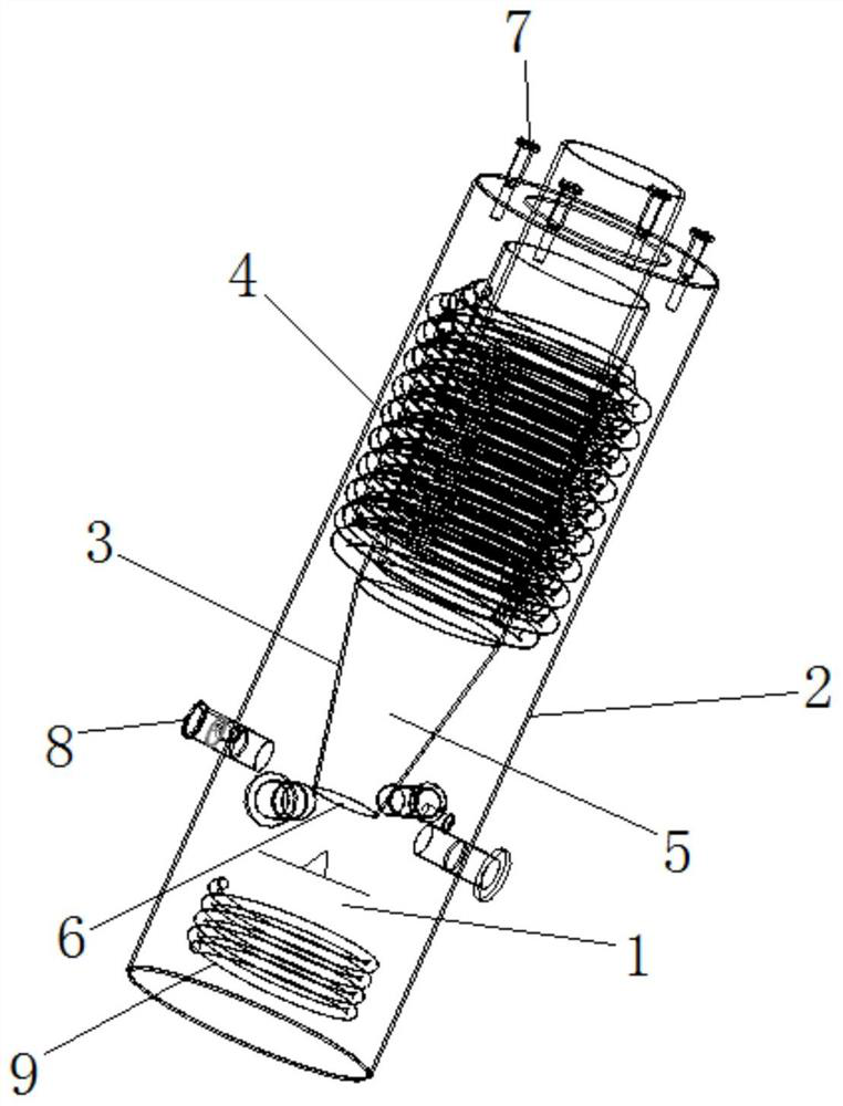
[0032] In order to solve the problem of insufficient heat and moisture exchange between flue gas and water in the original gasifier, this embodiment adopts the spray humidification method, and adopts the multi-nozzle top and middle mode to reduce the energy consumption of the fan and increase the heat exchange efficiency. The structure of gasification equipment is as follows Figure 1 to Figure 3 shown.

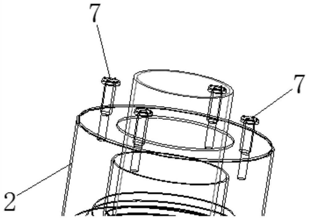
[0033] First, four overhead nozzles 7 are arranged on the top of the gasifier. The water source of the overhead nozzles 7 comes from the bottom pool 1, and the temperature of the water in the bottom pool 1 rises due to the heating of the high-temperature flue gas. The circulation pipe 9 reaches the overhead nozzle 7 and sprays out from the overhead nozzle 7. The multi-nozzle overhead method is used to effectively use the space on the top of the gasifier and improve the utilization rate, and the number of spray structures should not be too large. When the number of nozzles is...

Embodiment 2

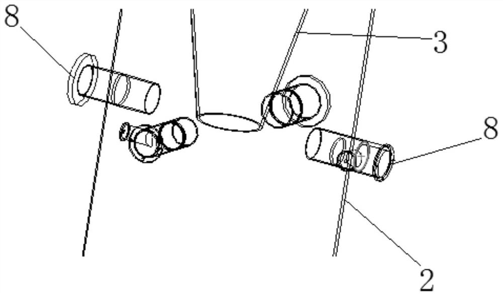
[0038] like figure 1 A gasification device with a spray structure is shown, including a gasifier body, an overhead nozzle mechanism set on the top of the gasifier body, and a middle nozzle mechanism set on the side of the gasifier body. The gasifier body The interior of the tank is provided with a bottom pool 1, and the overhead nozzle mechanism and the middle nozzle mechanism communicate with the bottom pool 1 respectively.

[0039] Wherein, the gasifier body includes an outer cylinder body 2, a fire tube 3 arranged inside the outer cylinder body 2 and above the bottom pool 1, and a heated tube bundle 4 surrounding the outside of the fire tube 3. A combustion chamber 5 is provided inside the fire tube 3. The heated tube bundle 4 is an upward coiled tube. The torch 3 is arranged vertically, and the bottom of the torch 3 is provided with a flue gas outlet 6 adapted to the bottom pool 1 .

[0040] like figure 2 As shown, the overhead nozzle mechanism includes a plurality of ...


PUM


Abstract

The invention relates to gasification equipment with a spraying structure. The gasification equipment comprises a gasification furnace body, an overhead nozzle mechanism arranged at the top of the gasification furnace body and a middle nozzle mechanism arranged on the side surface of the gasification furnace body, a bottom water tank is arranged in the gasification equipment, and the overhead nozzle mechanism and the middle nozzle mechanism are respectively communicated with the bottom water tank. Compared with the prior art, the invention aims at an existing gasification furnace, the sprayingstructure is arranged, the spray gasification techniques are introduced, the water heated by the flue gas is sprayed to a heated tube bundle at normal pressure; in addition, due to the evaporated andcondensed water after gasification, the heated tube bundle can be better promoted to be in full contact with water and flue gas, the problem of insufficient heat exchange is effectively solved, flowing of a gas field is increased in the gasification equipment, flowing of mixed gas of water and flue gas coming from the lower portion upwards is driven, and thus heat exchange is enhanced, and energyconsumption is reduced.

Description

technical field [0001] The invention belongs to the technical field of LNG gasification, and relates to a gasification device with a spray structure. Background technique [0002] At present, the utilization of natural gas is becoming more and more extensive. As the "fist project" natural gas pipelines of China and Russia have been connected and ventilated, the preheating treatment of natural gas is becoming more and more important to further improve the thermal efficiency of natural gas gasifiers . [0003] In the existing LNG gasification equipment, when the water in the bottom pool is in contact with the heat exchange tube after gasification, there will be some cases of insufficient contact, resulting in insufficient heat exchange process, low heat exchange efficiency, and unstable gasification. And it brings waste of energy consumption, which eventually leads to the uncontrollability and unpredictability of gasification heat and mass transfer. Contents of the inventio...

Claims


Application Information

Patent Timeline
Patent Type & Authority Applications(China)
IPC IPC(8): C10L3/10C10L3/12B01B1/00
CPCB01B1/005C10L3/10C10L3/12C10L2290/04
Inventor 郭韵陈昊
Owner SHANGHAI UNIV OF ENG SCI
Why Eureka
Try Eureka